


Applying a Custom Rebar Layout in RISA-3D:
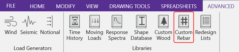
To begin creating a custom rebar layout, simply click the Custom Rebar Layout button located in the Advanced tab of the ribbon toolbar.
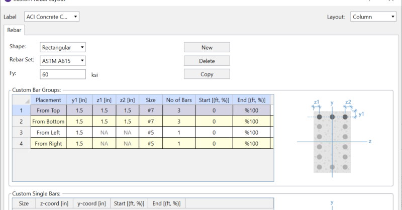
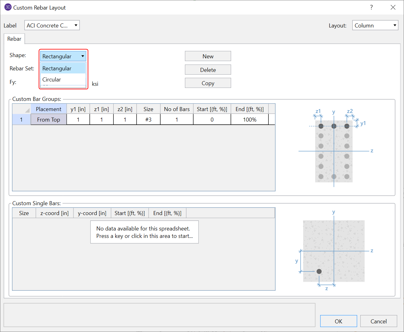
In RISA-3D, within the rebar layout dialog you can create a custom rebar layout for concrete beams, concrete columns and even create a custom shear rebar layout. Using the rebar layout editor is very easy and the following example will demonstrate creating a custom rebar layout for a rectangular concrete column. Click “New” to create a new rebar layout and create a label for the layout.
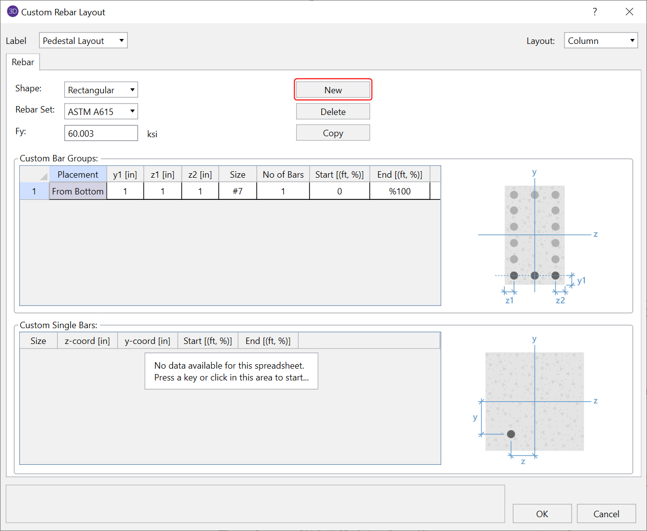
Select whether the rebar layout is for a rectangular column or circular column. You can also choose the rebar standard and yield stress for your custom rebar configuration.
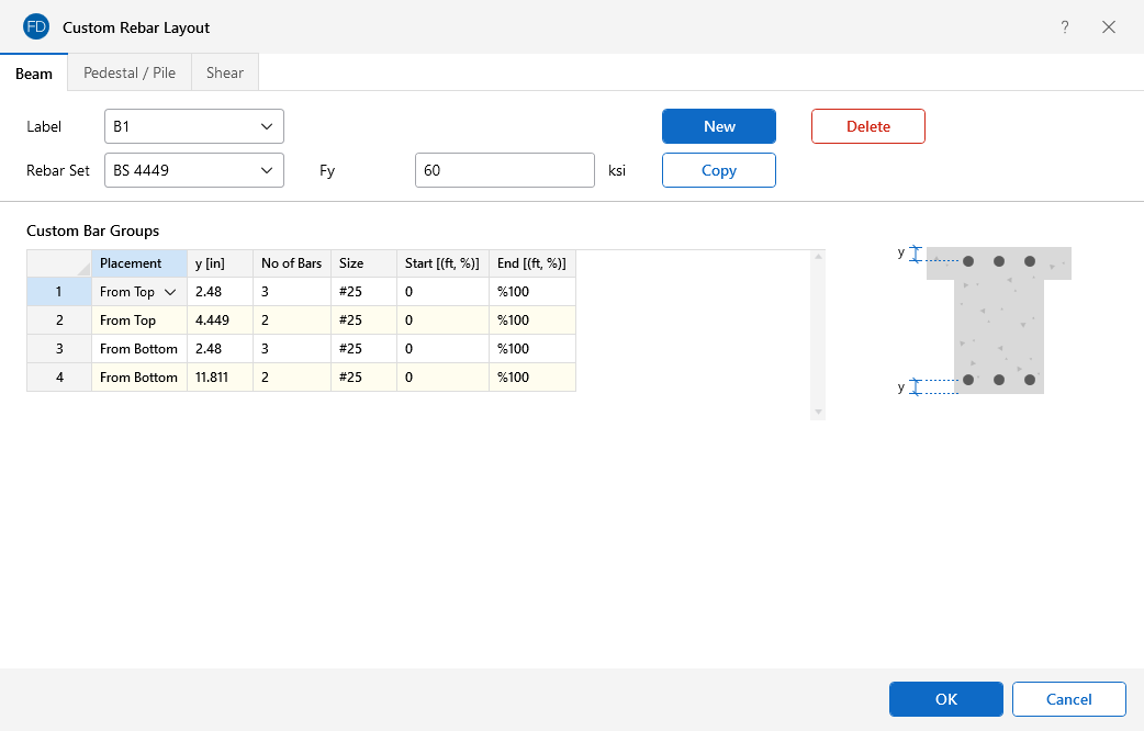
To create the reinforcement layout, input the parameters into the spreadsheet to configure each row of rebar. Each parameter is explained below:
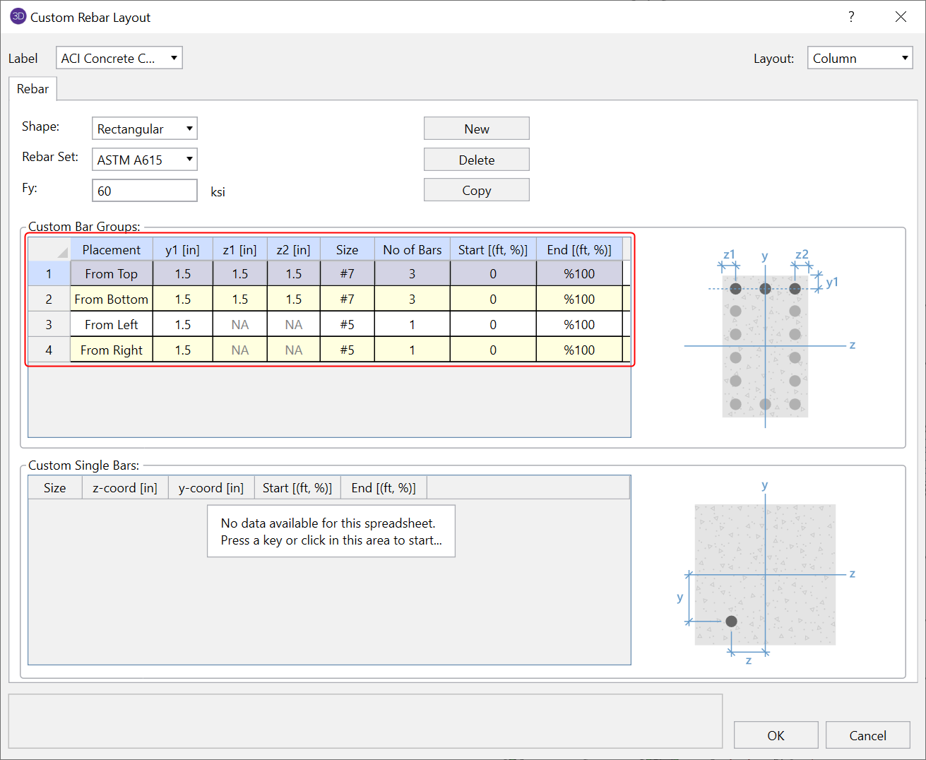
1. Placement: This is the direction that will determine where the reinforcement will be measured from (based on the reference graphic).
-
Top or Bottom: The row of reinforcement will be measured from the top or bottom of the concrete member and will distributed the number of rebar horizontally and evenly between the concrete cover.
-
Left or Right: The distance to the centerline of rebar will be measured from the left or right side of the member and the number of bars will be distributed vertically.
2. y1 [in]: Distance to the centerline of the reinforcement row
2. z1 [in]: This is the distance from the left side of the member to the centerline of left-most rebar within the given row of reinforcement.
3. z2 [in]: This is the distance from the right side of the member to the centerline of right-most rebar within the given row of reinforcement.
4. Size: This is the size of the rebar within the given row of reinforcement
5. No of bars: Number of rebar within the given row of reinforcement.
6. Start [ft,%]: This is the distance along the length of the member where the reinforcement will star. This can be entered as a length or a percentage of the member’s length.
7. End [ft,%]: This is the distance along the length of the member where the reinforcement will end. This can be entered as a length or a percentage of the member’s length.
Applying a Custom Rebar Layout in RISA-3D
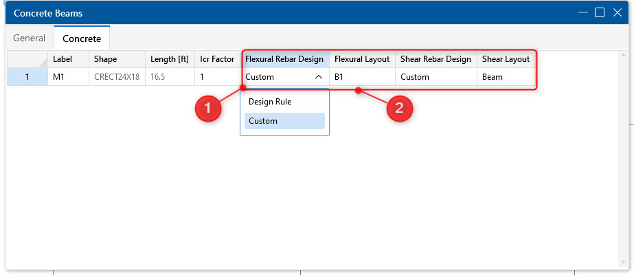
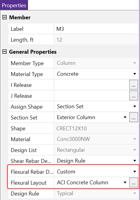
To apply your custom layout, select a member in the graphical interface and then in the "General Properties" section of the "Properties Panel" change the "Flexural Rebar Design" field to "Custom" while selecting your custom "Flexural Layout". You can also do the same for the "Shear Rebar Design" as well.
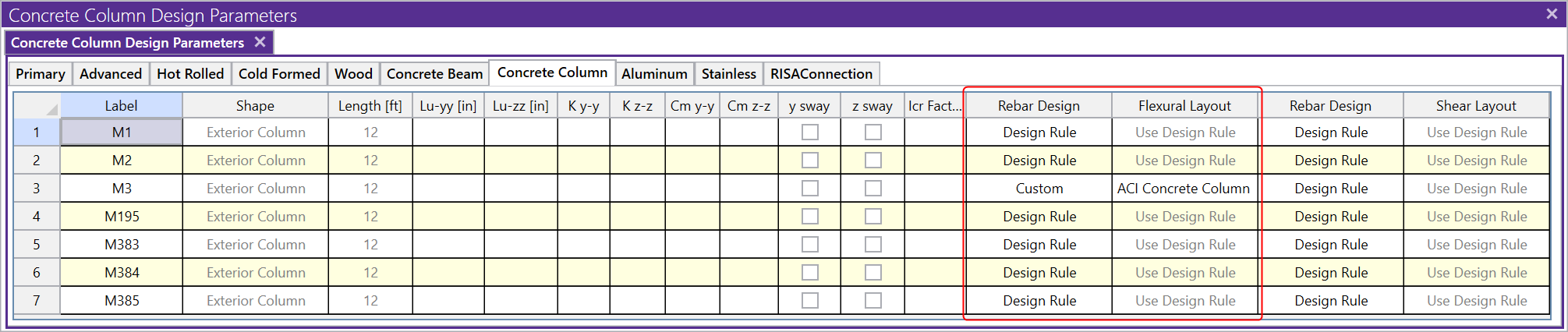
Alternatively, you can open up the "Members" spreadsheet and select the "Concrete Column" tab to modify the properties in table form.
Applying a Custom Rebar Layout in RISAFoundation
In RISAFoundation, clicking the Custom Rebar Layout icon will open the rebar layout editor where you can create new layouts for bending rebar, shear rebar and pedestal/pile rebar.
Similar to RISA-3D, you can specify the custom rebar layout from the corresponding spreadsheet.