


RISA-3D Version 19 now includes the ability to define the plate methodology of a material as orthotropic. In structural analysis and design, it may be useful to define plates or slabs that have different characteristics (stiffness) in the longitudinal and transverse directions. Doing so will result in the plates reacting to loading differently in different directions. This type of behavior can be useful when defining metal decks, cross-laminated timber or ribbed slabs.
To utilize orthotropic plate behavior, the user first needs to select the General tab of the Materials spreadsheet or open the Edit Material Dialog when adding a plate.
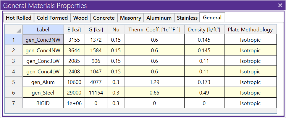
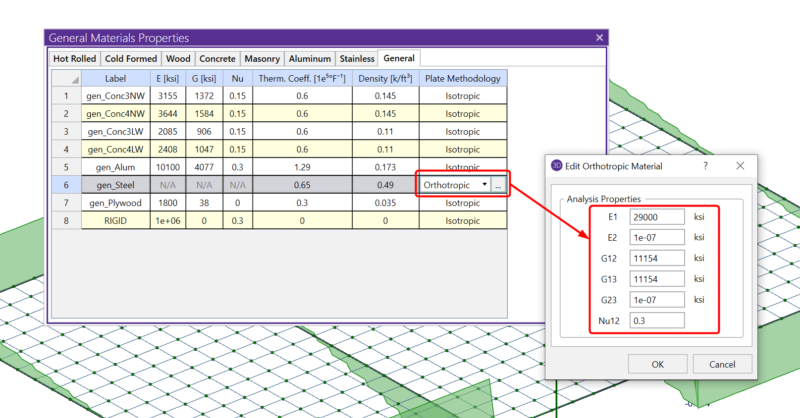
A new option for Plate Methodology has been added for each General material where users can select between Isotropic (standard material/plate behavior) and orthotropic. When orthotropic is selected, users must click on the ellipsis button (3 dots) located within the specified cell in order to access the analysis properties for the material.
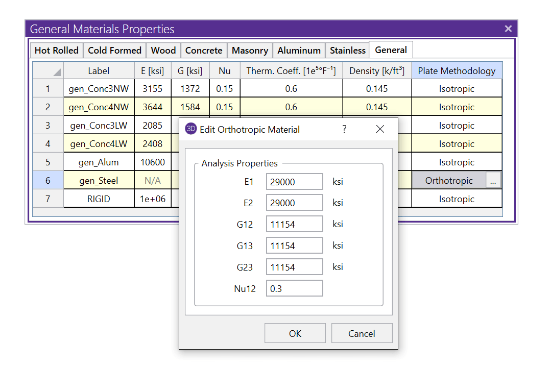
The properties of the material can be adjusted as needed in order to achieve the desired plate stiffness and load distribution.
The various properties available are as follows:
-
E1 = Modulus of elasticity in longitudinal direction (also defined as the “1” direction or local x direction)
-
E2 = Modulus of elasticity in transverse direction (also defined as the “2” direction or local y direction)
-
G12 = In-plane shear modulus
-
G13 = Transverse shear modulus for shear in XZ plane
-
G23 = Transverse shear modulus for shear in YZ plane
-
Nu12 = Poisson’s ratio (for uniaxial loading in X direction)
A few notes about the analysis properties:
-
All values should be input as real values where necessary.
-
If no calculated value is available for G13 and G23, the value of G12 may be used.
-
If G12 and G23 are zero or left blank, then transverse shear flexibility calculations will not be performed, which is equivalent to zero shear flexibility (ie. infinite shear stiffness).
-
The input values need to satisfy the equation 1 - (Nu12*Nu21) > 0, where Nu21 = E2*N12/E1.
-
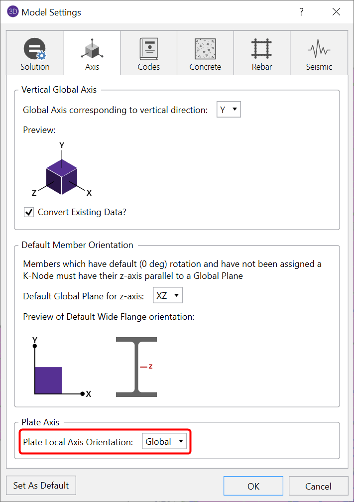
When orthotropic material is used, the Plate Axis option found in Model Settings must be set to Global.
Example - One Way Deck
One of the main use cases for orthotropic material properties is to simulate one-way deck/slab behavior. In the example below, a simple bay has been created and a plate surface load has been applied in the vertical downward direction (local z direction). Additionally, the plate material specified is the thickness of the metal deck material as specified by the deck catalog.
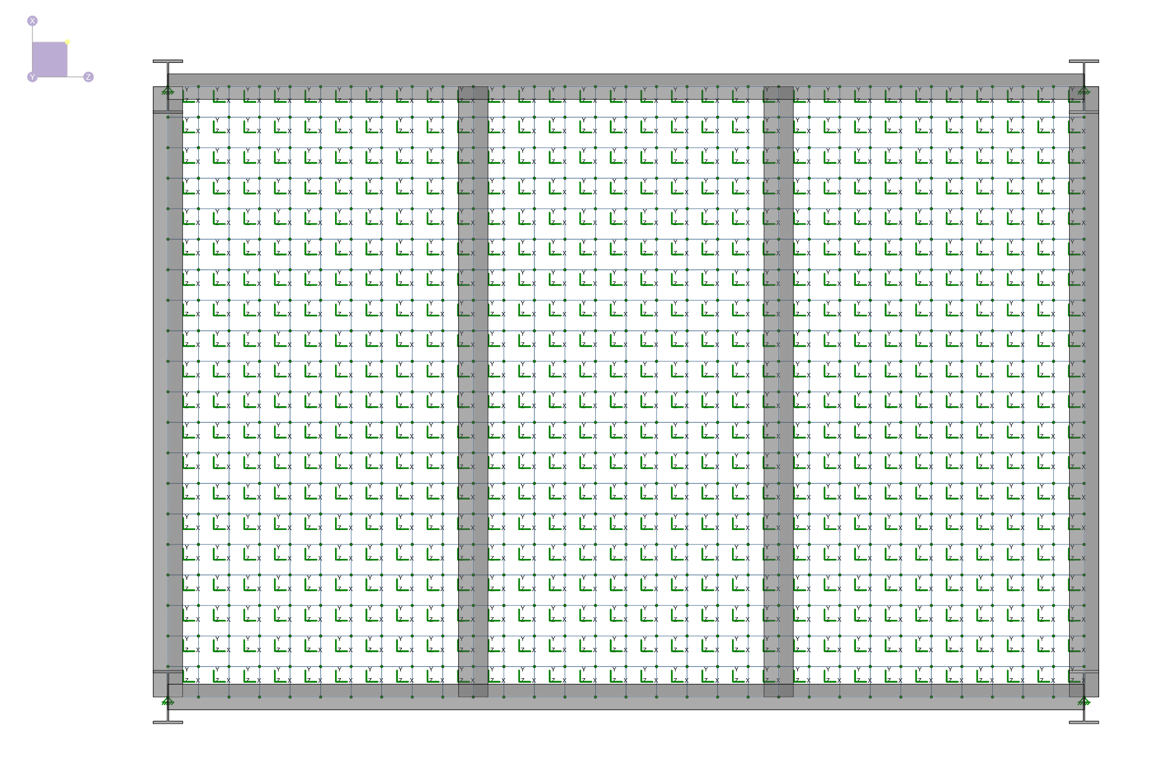
As a result of the framing the load transfer we desire is in the global Z direction with the decking spanning from beam to beam in the Z direction. To achieve this behavior, the orthotropic properties of the gen_steel material that is being used can be adjusted.
To do this, select a single plate and then click the ellipsis (3 dot) button found in the Material portion of the Property Window. Next, choose to Edit the Existing Material and the following Edit General Material dialog will be displayed:
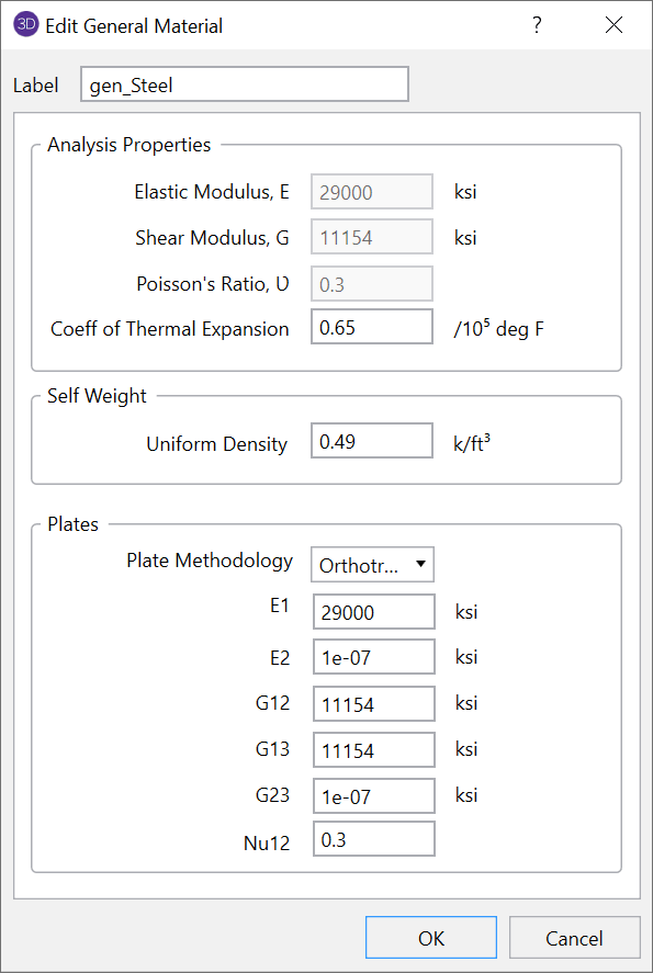
Within the orthotropic plate methodology, the most straightforward approach to create this one-way behavior is to modify the values for E2 and G23. Because E1 corresponds to stiffness in the local x direction, we want to maintain the value of E1 as prescribed in the generic steel material and reduce the value of E2 (stiffness in the local y direction) to a value near zero (RISA allows for a minimum value of 1E-7). Additionally, we also want to reduce the transverse shear modulus in the YZ plane (perpendicular to the direction of the load transfer we desire) to a value near zero (RISA allows for a minimum value of 1E-7). Once the values have been set, click OK.
With the values set properly, run the solution in order to review the results (specifically the value of y shear) to show the one-way load distribution.
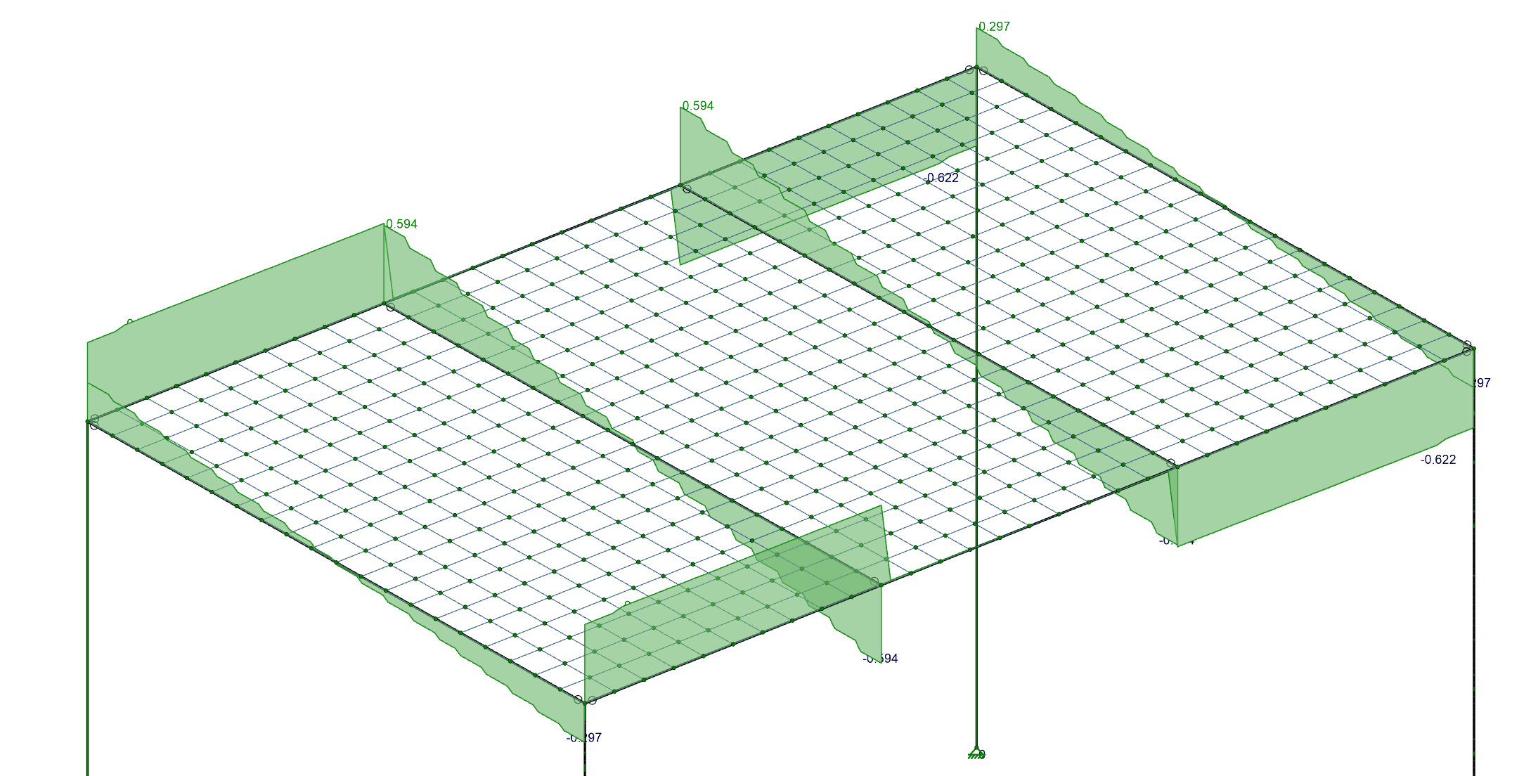
Note: The size of the mesh used will impact the distribution of forces. With the connection between plates made only at the plate corners, the larger the plates, the less precise the load distribution will be as compared to pure one-way action. Make sure to use an adequate mesh size to achieve the desired load distribution as compared to the hypothetical results, while being aware that a smaller mesh results in a larger model and longer solution time.
For more information about orthotropic plates, check out our video posted on YouTube: