


When using semi-rigid diaphragms in a RISAFloor/RISA-3D model, it is possible to see negative moments at the ends of pinned beams as a result of the link between the semi-rigid diaphragm and the beam-column connection.
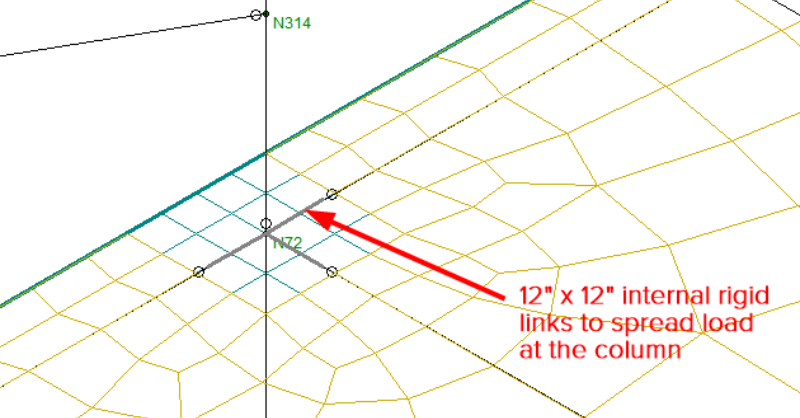
In RISAFloor, semi-rigid diaphragms utilize internal rigid links to create a 12in by 12in “rigid zone” around the column location in order to spread the load from the column out to the diaphragm. This prevents the load from being applied to the diaphragm at just the single node (which is unrealistic) that represents the column to slab attachment. Although this assumption achieves a smooth load application between the column and the slab, it can result in “spikes” in member end forces that are unexpected if the member end falls within the “rigid zone”.
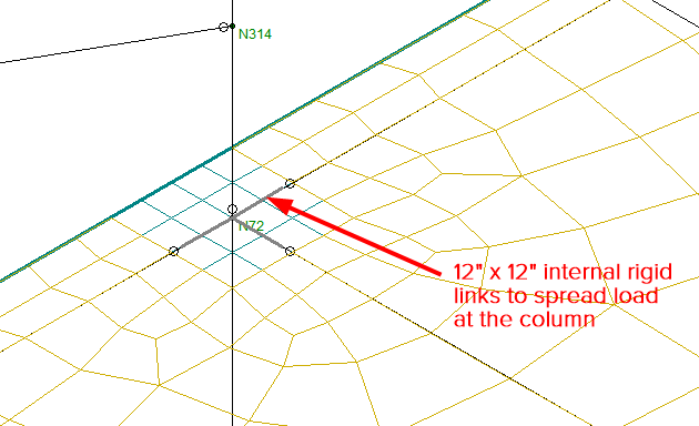
Note: When developing semi-rigid diaphragms in RISAFloor/RISA-3D, a 12in by 12in footprint was chosen because it was assumed that most columns would fall within that region. Additionally, a specific footprint was chosen (rather than one determined by the explicit size of a column) which allows RISAFloor to continue with the design and optimization routines without having to re-iterate the mesh.
When this situation arises, engineers can either determine that these spikes are negligible and therefore can be ignored or add additional eccentricity to the beams to move the member ends outside of the “rigid zone”. To do this, the following steps can be used:
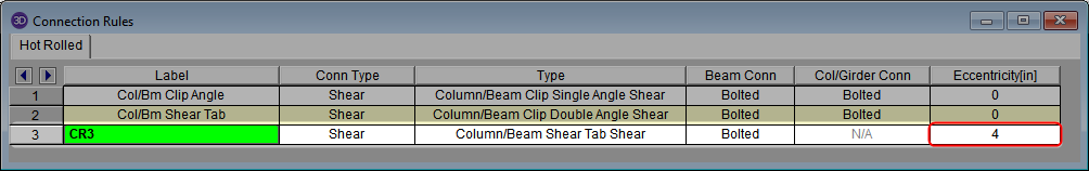
1. Add eccentricity to a desired Connection Rules
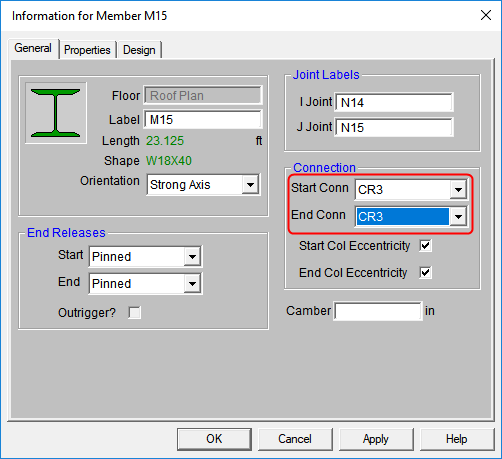
2. Assign the Connection Rule to the member end
3. Review the total eccentricity (I/J offset) in the Advanced tab of the Members spreadsheet. The eccentricity will be added to the existing column eccentricity.
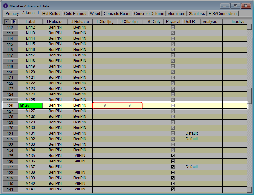
Note: Column eccentricity can be set by either using the Start/End Col Eccentricity option in RISAFloor or by manually inputting an I/J offset in the Advanced section of the Member Properties in RISA-3D. However, be aware that adding additional eccentricity to the beam member end will induce additional moment in the connecting column.
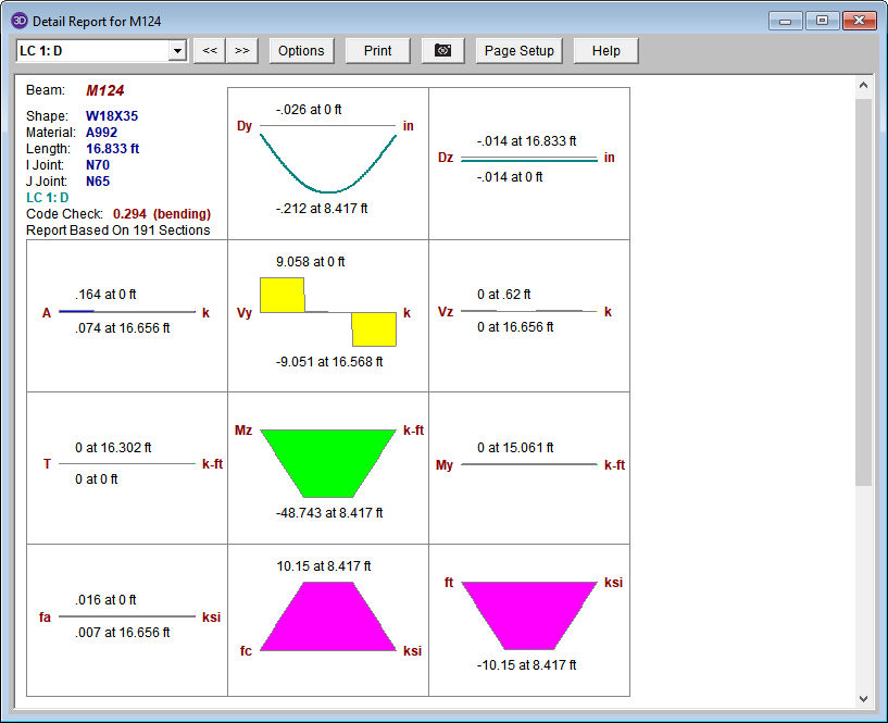
Once the additional eccentricity has been added, the Detail Report can be reviewed to show that the moment and shear diagrams are drawn as expected now that the member end falls outside of the “rigid zone”.
For more information about using I/J offsets in RISA-3D, see the article How to Define a Beam to Column Eccentricity in RISA-3D & RISA-2D.

For more information about assigning eccentricity to connections, visit our Help section on Connections – Eccentricity.
