


ADAPT-Builder is a three-dimensional free-form finite element software for structural concrete modeling and analysis. Structural components in ADAPT-Modeler do not have to be input along grid lines or at connective, adjoining node locations as is the case in most other structural engineering software on the market today. ADAPT-Builder's free-form modeling allows the user to model and represent the true physical structure, as compared to an analytical representation.
To facilitate this flexible modeling, the ADAPT-Mesher will consolidate nodes of considered components using its "Node Consolidation" feature. This feature allows the user to set a maximum distance for node consolidation and the software will consolidate nodes within the define proximity. The Node Consolidation (Node Shift) feature is described in more detail in the ADAPT-Floor Pro 2019 Basic Manual (linked below). When node shifting, the program accounts for the eccentricity between the modeled location of the element and the analytical location of the element. In most cases this feature is effective, and the program will consolidate nodes and produce a mesh. However, as the program allows the modeling of very complex geometries, there are times where the mesher fails to produce a mesh.

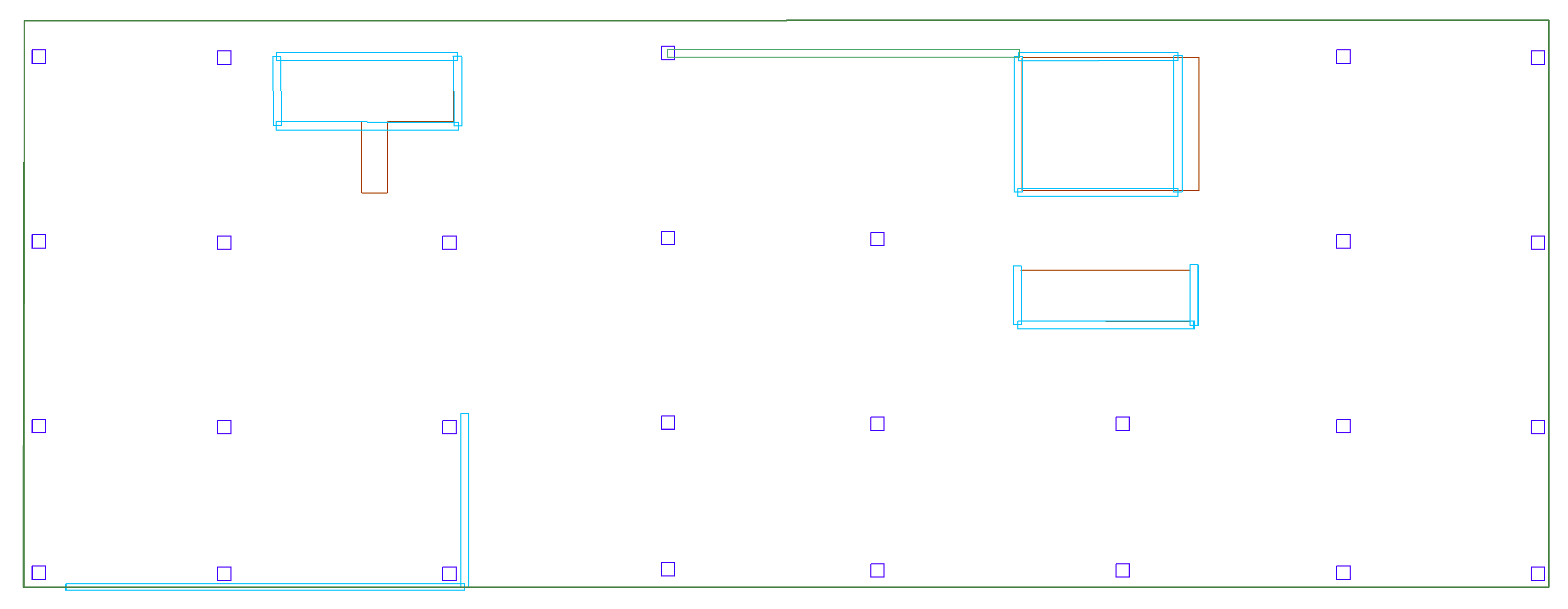
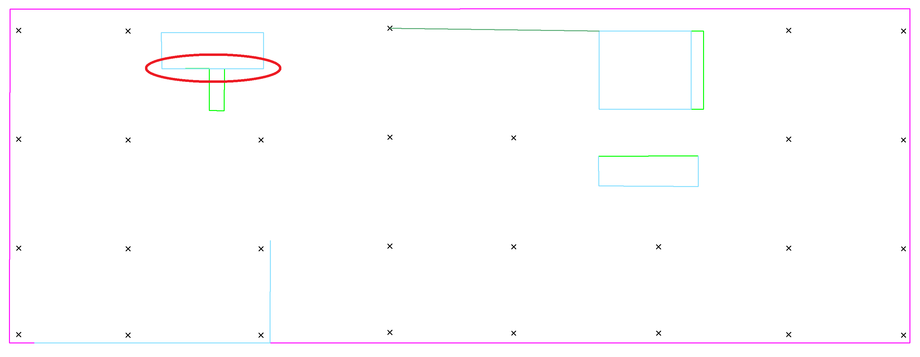
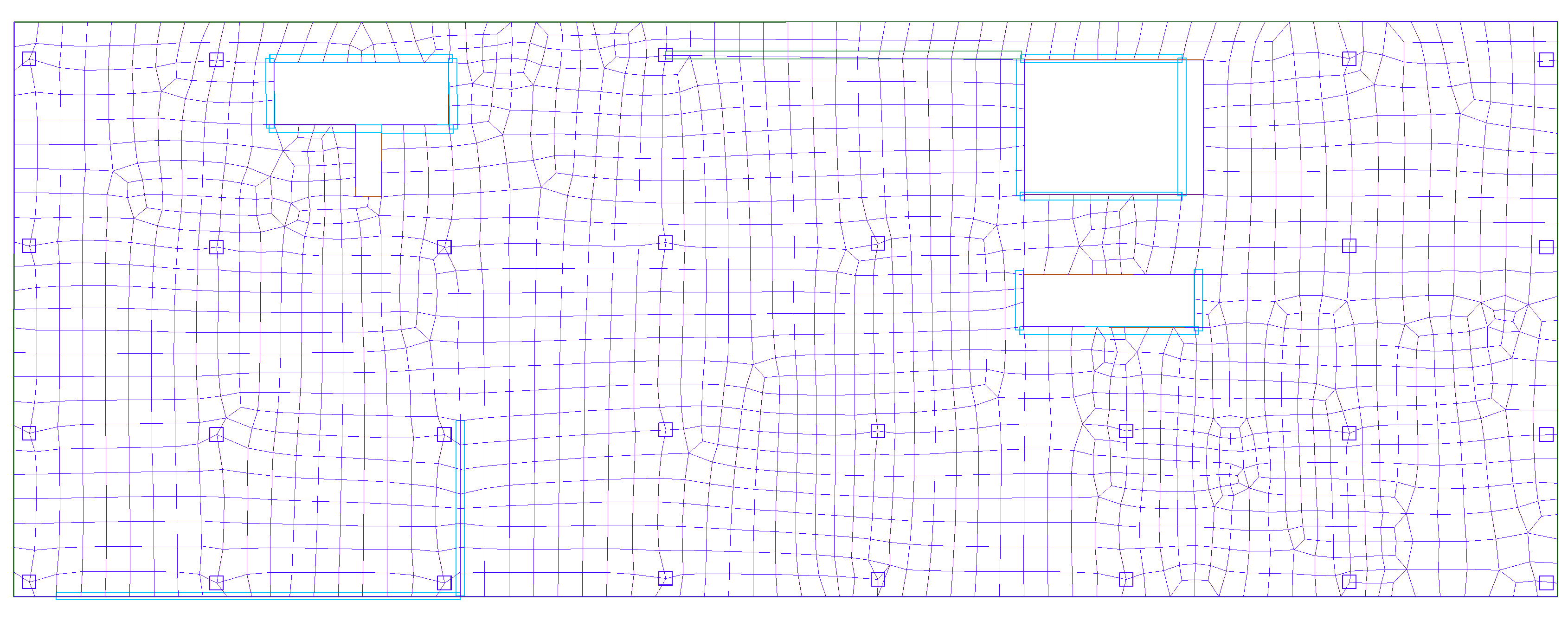
When the mesher fails, the user is prompted with an error message followed by a drawing consisting of lines of multiple colors, and points marked as an X on screen. These lines and points are called Component Representatives. Each component representative line or point represents the analytical line or point of a component in the model that the program must mesh to for proper analytical consideration of the represented component. These lines and points will follow the longitudinal axes and centroids of the component, or in the case where the component’s nodes have been shifted, will follow the node(s) of the component. An example of a physical model and its component representatives are shown in the following figures.
Physical Model
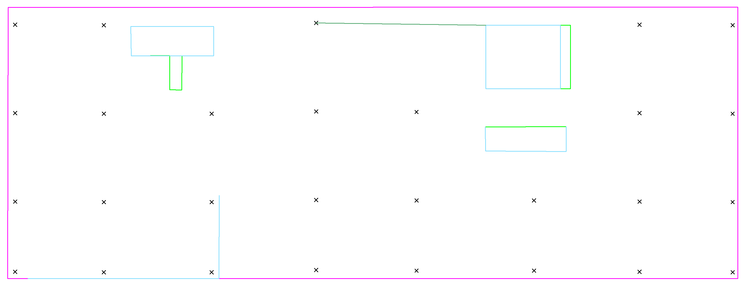
Component Representative
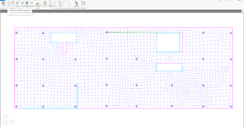
The component representatives are only created upon failure of a mesh and are for the model at that state in time in which it failed to produce a mesh. The component representatives will not update automatically when a user changes the model, they are only updated when the mesh fails or when the user invokes the manual meshing tool. Component representatives can be turned on and off in the software by navigating to Analysis > Meshing > Display/Hide Component Representatives.
The color of the analytical line or point correlates it with the component it represents. The correlation is as follows:
-
Slab Regions – Magenta Lines
-
Walls – Cyan Lines
-
Beams – Dark Green Lines
-
Openings – Bright Green Lines
-
Columns – Black X
-
Drop Caps/Panels – Red Lines
When the mesher fails to produce a mesh, the software will turn on the component representatives for the user to review. Reviewing the component representatives can point to locations where the program has difficulty meshing. In the previous figure, the model had failed to mesh and then displayed the component representatives on screen. Reviewing the displayed component representative can facilitate investigating locations where the mesher may have to step down to a size the mesher cannot produce cells for. We can see one area where this occurs in this example at the location shown circled in red below.
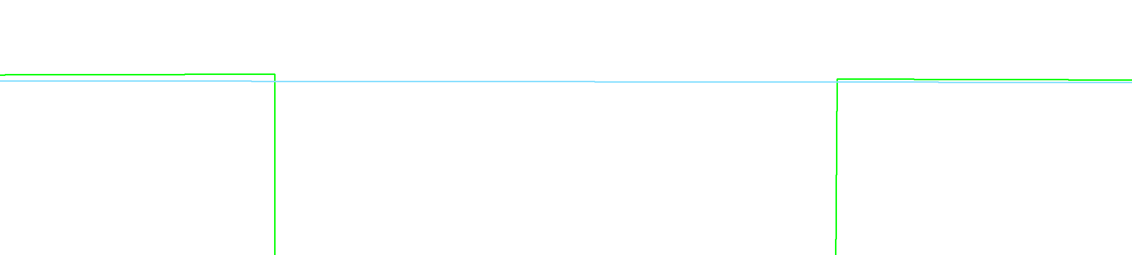
Zooming into the location circled above, we can see the component representative for the wall and the component representative for the opening are not aligned. The gap between them is an area the program must mesh to but cannot. The distance between them is too small to meet the mesher’s internal tolerance for mesh production.
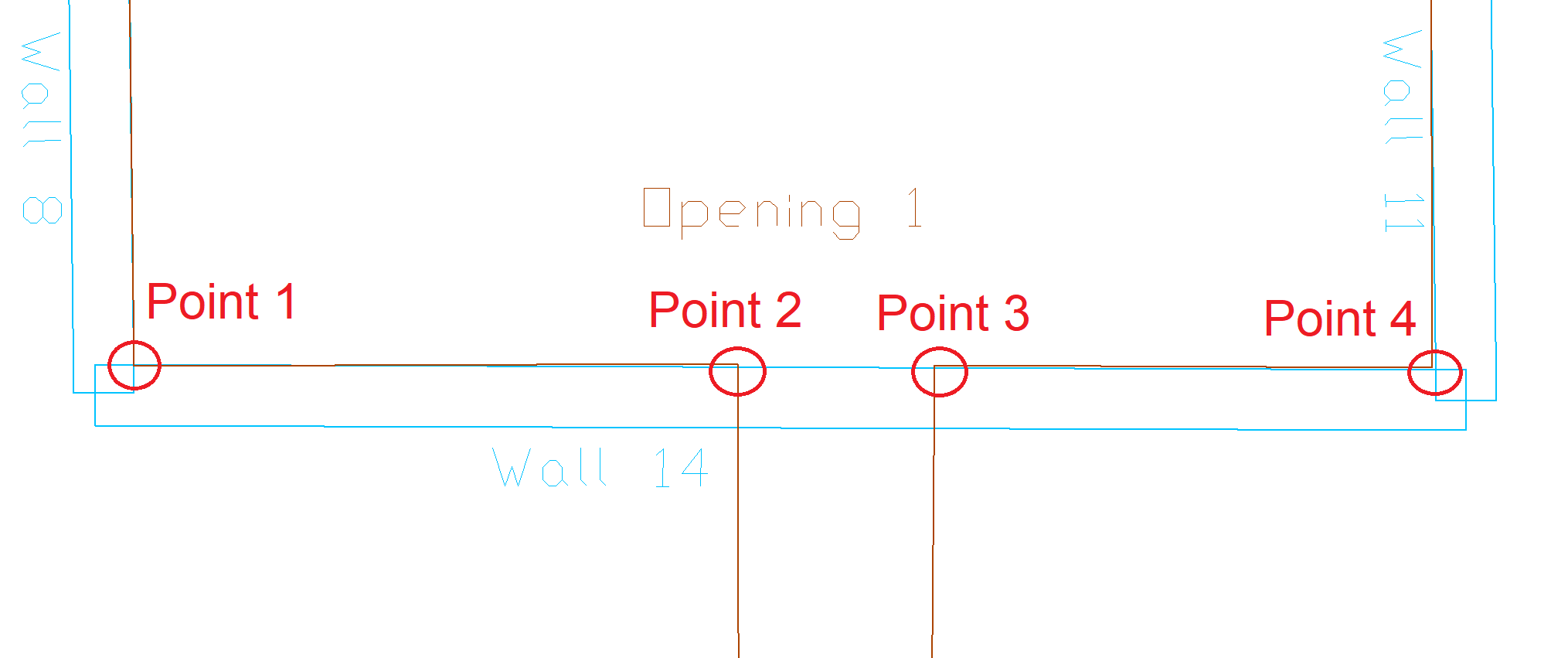
The reason for this is that the opening points (along the line of the wall) are not aligned orthogonally with the wall. The wall shifts to the first and fourth point of the opening along this wall, however, the second and third points defining the opening along this wall are not snapped directly along the line between points one and four. The user can see this in the zoomed view of the physical model shown below as well, however, the component representatives make this easier to see.
The user has two options to fix the modeling such that the program can mesh the structure. The first option is to meticulously align the points of the opening along the edge of the wall using the modeling tools of the software. This can be time consuming depending on the complexity of the location. The second option would be to break the wall into three segments to match the change in the slab due to the opening as shown below.
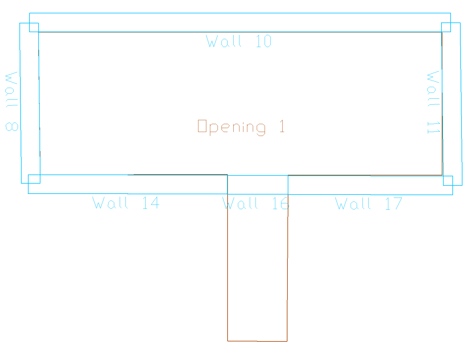
Modeling in this fashion the program can shift the nodes of each wall segment to the corresponding point along the opening. Once this change has been implemented the program can mesh the model without issue.
In conclusion, component representatives are a commonly seen, rarely understood, but useful feature of the software. A basic knowledge of component representatives and how they relate to the mesh can greatly improve the user’s ability to locate and resolve meshing failures within their model.