When the mesher cannot converge to a mesh, you are prompted with an error message followed by a drawing consisting of lines of multiple colors, and points (marked as an X) on screen. These lines and points are called Component Representatives. Each component representative line or point represents the imposed location of a component's nodes in the model. The finite element mesh cells must align with these locations for proper analytical consideration of the represented component. These lines and points, by default, will follow the natural node location along the longitudinal axes and centroids of the component. In the case where the component’s nodes have been shifted, these lines will follow the imposed location of the node. An example of a physical model and its component representatives are shown in the following figures.
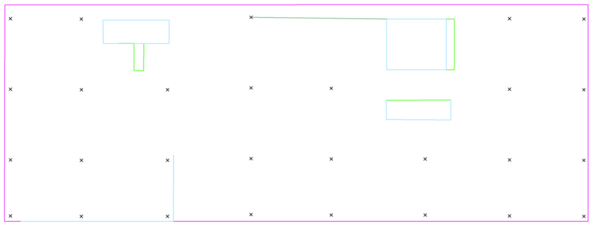
Physical Model:
Click image to enlarge
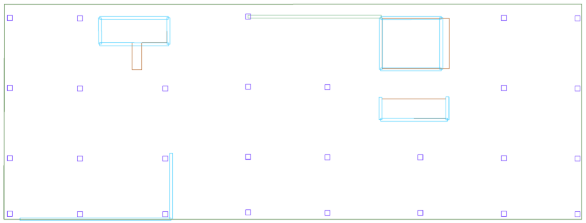
Component Representatives:
Click image to enlarge
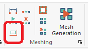
The component representatives will not update automatically when a you make changes to the model. You must either have the ADAPT-Mesher fail to converge to a mesh or Generate a Manual Mesh for the component representatives to be updated. Component representatives can be turned on and off in the software by navigating to the Analysis ribbon Meshing panel and clicking on the Display/Hide Component Representatives icon.
The color of the analytical line or point correlates with the component it represents. The correlation is as follows:
Slab Regions – Magenta Lines
Walls – Cyan Lines
Beams – Dark Green Lines
Openings – Bright Green Lines
Columns – Black X
Drop Caps/Panels – Red Lines
To diagnose mesh errors using component representatives:
Component representatives are a set of points and lines the program must mesh to in order to capture the physical model geometry. Please review the Component Representatives topic of this help menu for more information.
You can review the component representatives for locations that might be difficult for the program to mesh to, based on the suggested cell size input by you. At these locations, you should then turn off the component representatives and review the physical model geometry to see if there is a way to simplify the geometry in the problematic areas you have identified through a review of the component representatives. It is recommended to zoom in and review the component representatives up close to be able to identify problematic locations easier. An example of component representatives of a model is shown in the image below.
Click image to enlarge
If we zoom into the core wall and opening at the top left, we can see that the component representative lines representing the wall and the openings here diverge from each other creating a small area where the program will likely have difficulty converging to a mesh. These areas are marked in red in the image below.
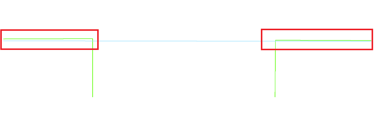
Click image to enlarge
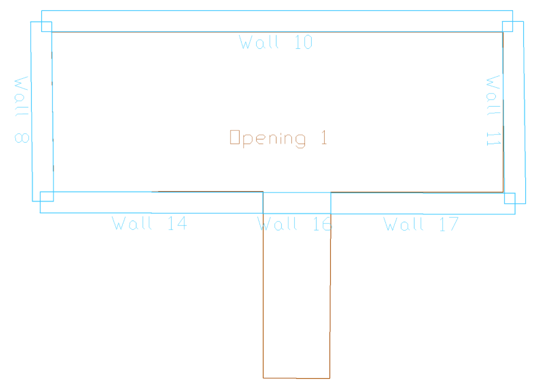
We can then turn off the component representative by clicking on the Display/Hide Component Representatives  icon found in the Analysis ribbon Meshing panel, and turn on the physical model through the Visibility Grid to review if the physical model can be simplified. The image below shows the physical model in this location with the component representatives turned off.
Click image to enlarge
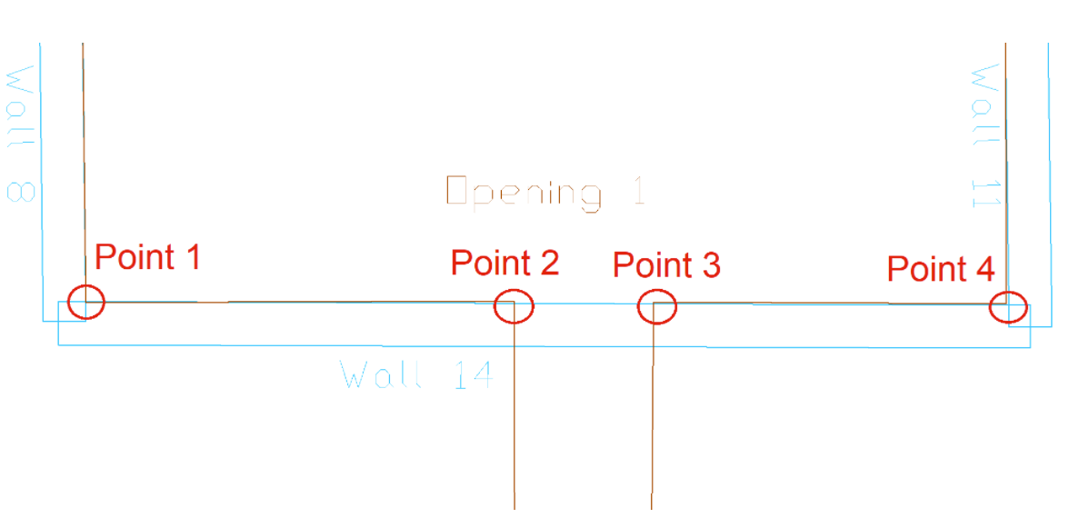
In the above image we can see the wall is modeled as one long wall component and crossing over opening edges that are not aligned. To fix the issue we can choose one of the following methods.
Make sure the segment of the opening marked by point 1 and point 2 are aligned with the opening segment defined by point 3 and point 4. This way the wall can be shifted from point 1 to point 4 and remain in line with points 2 and 3.
We can break the wall up into three segments, one segment spanning point 1 to point 2, one segment from point 2 to point 3, and one segment from point 3 and point 4. Breaking the wall up allows the program to shift the nodes of the wall segments individually. In this case the alignment of the opening edge will not need to be as exact to allow the program to converge to a mesh. The image below shows an example of the physical model where we broke the wall up to assist the program in converging to a mesh.
Click image to enlarge
We can now have the program attempt the Automatic Mesh Generation again. Go to the Analysis ribbon Meshing panel.
Click on the Mesh Generation  icon.
icon.
Set the settings you wish to use for your mesh.
Click Save & Mesh Slabs button to attempt the automatic mesh again.