Model in a fashion that is conducive to meshing, this includes:
-
Extend the Boundaries of Openings to Centerline of Adjacent Walls
For purposes of analysis, it is recommended that you extend the side of the openings with perimeter walls or beams to the centerline of the walls or beams that form the opening’s boundary.
Click image to enlarge
-
Extend Openings to Slab Edge
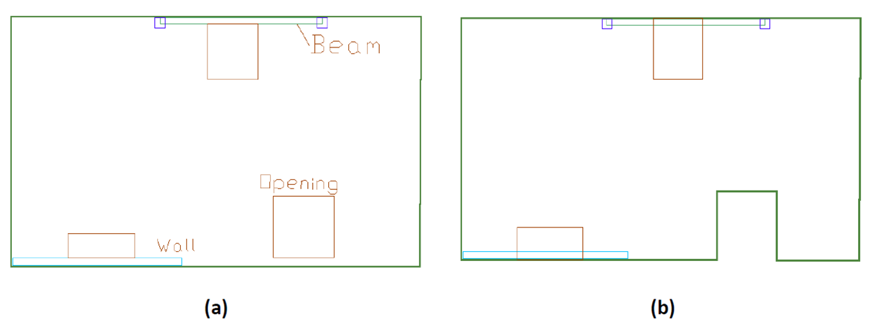
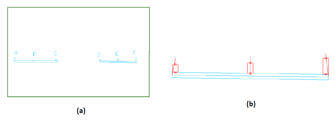
Where openings are next to the slab edge, such as shown in three different scenarios in part (a) of the image below, extend the opening to the slab edge.
The extension is justified where the narrow slab band between the opening and slab edge does not make a notable difference in the load carrying capacity of the floor.
Part (b) of the figure shows the treatment in each of the below scenarios.
-
If the strip of slab band between the opening and slab edge is not supported, move the slab boundary around the opening.
-
Where a wall or a beam separates the opening from the slab edge, extend the opening to the slab edge, with no modifications in either the wall or the beam. The analysis will automatically mesh the beam and the wall, forming the outer boundary of the opening. The contribution of the beam and the wall on the outer edge of the opening will be fully accounted for by the program.

Click image to enlarge
Click image to enlarge
-
-
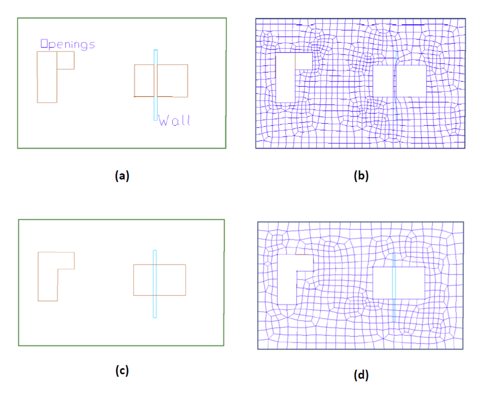
Combine Adjacent Openings
When two or more openings are next to one another, such as the two openings at the left of the figure below, it is best to combine them into one opening as shown in part (c) of the figure. If left as is, an unnecessarily denser mesh can result (part (b) of the figure).
Likewise, when two openings are drawn, one on each side of a wall or a beam, it is best to combine the openings as shown in part (c) of the figure. When combined, the program correctly accounts for the continuity and load carrying features of the wall or beam that passes through the opening.
Click image to enlarge
-
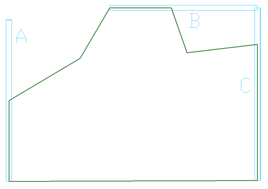
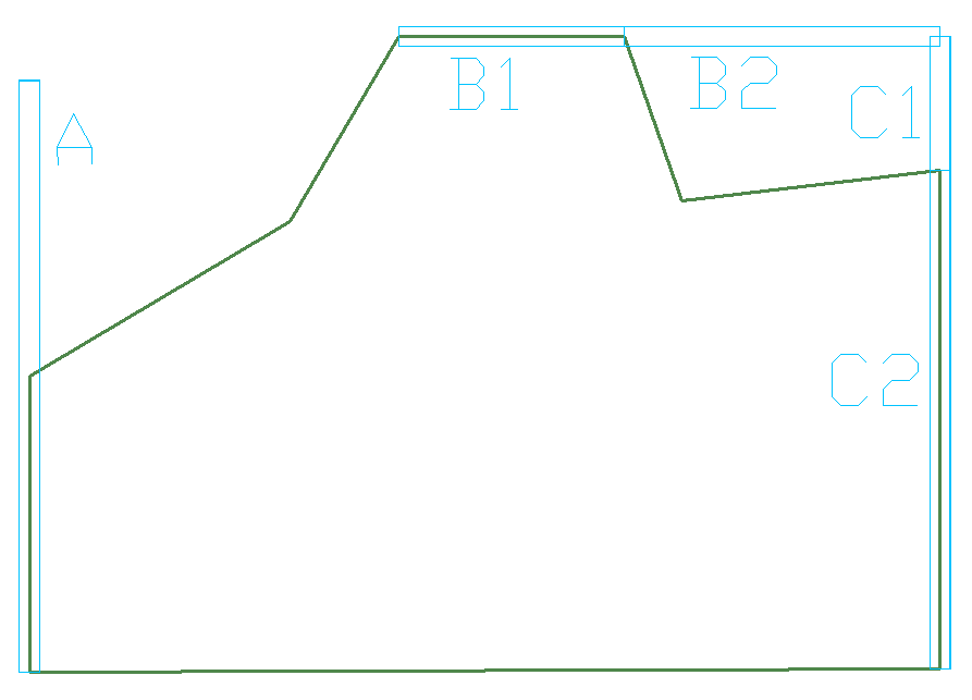
Break Up Walls and Beams that Intersect Outside a Slab Region
The image below shows a slab region with three walls A, B and C. Wall A does not intersect with another wall outside the slab area. This wall does not need special treatment. Walls B and C, however, intersect at a point outside the slab region. You must break each into two segments, one being the length within the slab region, and one outside it, as shown in the second image below. In other words, walls, or portions of walls, that fall outside a slab region should be modeled as a separate wall. This is a modeling requirement. From an analysis standpoint, the program will automatically consider the walls contiguous.
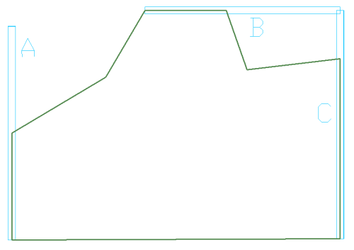
Click image to enlarge

Click image to enlarge
-
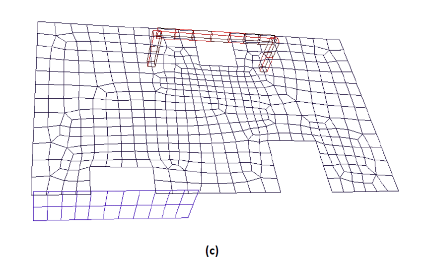
“Disregard” Short Wall Projections, or Use Manual Shift Node
In cases where short walls project from longer walls for reasons of architectural detailing, such as the example shown in the below image, there are a couple of options for their efficient modeling.
-
Bring the walls into your structural model, but disregard them in your analysis
-
Use manual node shift in order to simplify the modeling and avoid a dense finite element mesh.
The following provides more detail on these two options.
Disregard Option
If a wall is created to complete a structural detail, as opposed to carry load, such as projection B in the image below, change its component contribution input to “disregard” in the properties grid. This will retain the wall in your structural model for completeness; will not mesh it; will not consider its stiffness in resisting the applied load – but will consider it in the calculation of reinforcement and quantity take off. In other words, by selecting “disregard” you eliminate the inclusion of that wall in the formation of a stiffness matrix of the structural model, but account for its presence in other aspects of your work, including to resist the design values, such as moments and punching shear.
Manual Node Shift
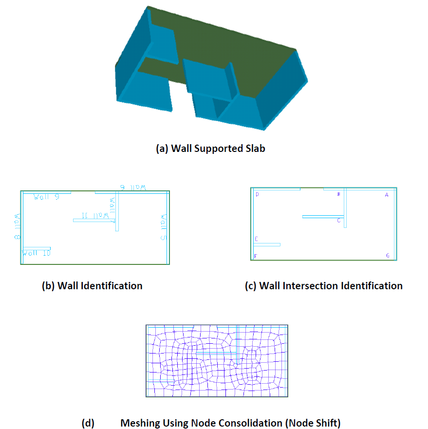
If a wall projection created to complete an architectural detail is large enough to have a notable effect on the local stiffness of the floor system, you may choose to retain it in your model. Select the “consider” option in the component contribution section of the property grid. In addition, the mesh density resulting from the inclusion of the wall projection can be improved if you manually consolidate its end node with that of the primary wall. An example of this option is shown in the projections D, E and F of the below image. This kind of node-consolidation is referred to as “manual node shift.” Please see the Node Shifting topic of this help menu for more information on shifting of component nodes. In the below image we can see the shifted axis of the wall projections D, E and F.

Click image to enlarge
-
-
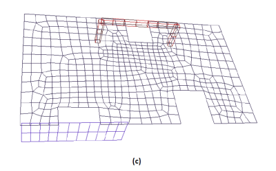
Treatment of Wall Intersections
There are several options to model the intersection of walls. These are illustrated in the following image. At “A” (part (c) of the figure), the walls intersect (overlap). Likewise, at “B,” Wall 7 is modeled to overlap with Wall 6. Wall 9 butts to Wall 8 at intersection “D.” Using the node shift option, the resulting meshing is shown in part (c) of the figure. Note that in all instances the intersection is consolidated into a common node. The difference between the various modeling schemes lies in the meshing and design of the wall itself. For example, for calculation of building weight and wall design, the length of Wall 10 is calculated to the face of Wall 8. But the length of Wall 5 is calculated to the outside face of Wall 6. That is to say, Wall 5 is assumed to extend over the entire width of the slab.

Click image to enlarge
-
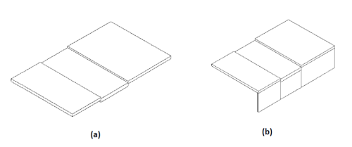
Break Walls Across Different Slab Regions
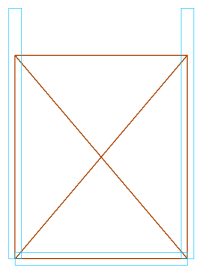
While not essential, where walls extend over more than one slab region, such as shown in the below image (b), you may break them into several walls for greater accuracy in your solutions. Break the wall, such that each sub-wall covers one of the slab regions. The wall in part (b) of the figure is continuous, but it is broken into three parts. When the Establish Component Connectivity tool of the program is invoked, the program automatically adjusts the top of each sub-wall to be in line with the soffit of respective slab region. The separation of the walls shown in part (b) of the figure does not affect the analysis of the structure. In the analysis, the walls that touch one another, such as the scenario in this case, will be considered contiguous and will be treated as one wall. There will be full compatibility of deformation among the sub-walls.
Click image to enlarge
-
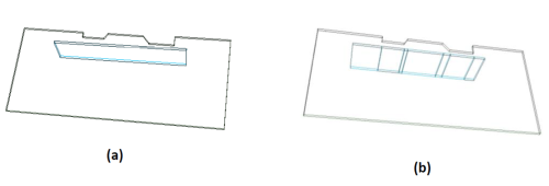
Break Up Walls and Beams Adjacent to Jagged or Irregular Slab Boundaries
Where a wall or a beam is close to a multiple discontinuity (jaggedness) at slab edge or opening, as illustrated in the image below, it may become necessary to break the wall up into sections. This is mostly the case, where the structural modeling is not done accurately, and a condition as shown in the figure below arises. The breakup is only necessary (i) if there is more than one protrusion or cut out along the slab edge, and (ii) if you invoke the node shift option of the program. When the node shift option is invoked, the program attempts to shift the analysis axis of the wall/beam onto the slab edge or opening. If the slab edge has many discontinuities, it would not be possible to line up the wall axis with more than one segment of the slab edge (or opening). For this reason, the wall has to be broken down into segments as shown in part (b) of the figure. The number of segments should correspond to that of the slab edge/opening adjacent to the wall/beam. Again, it should be noted that the breakdown of the wall is not necessary if the shift node option is not used. Also, for the analysis, the program will automatically consider the subdivided pieces of a wall/beam as a whole. In other words, the breakdown of a wall/beam into segments does not impact the solution, nor the treatment of the wall/segment as a contiguous member in resisting the load.
Click image to enlarge
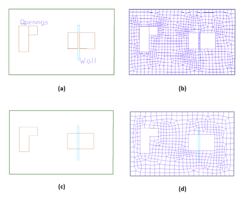
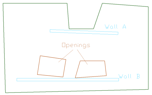
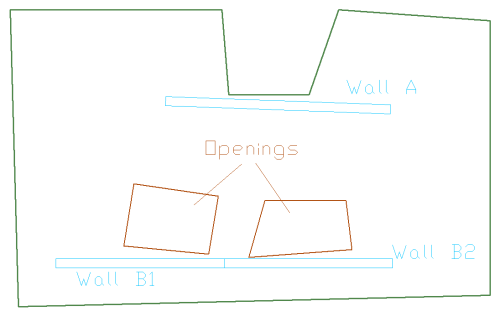
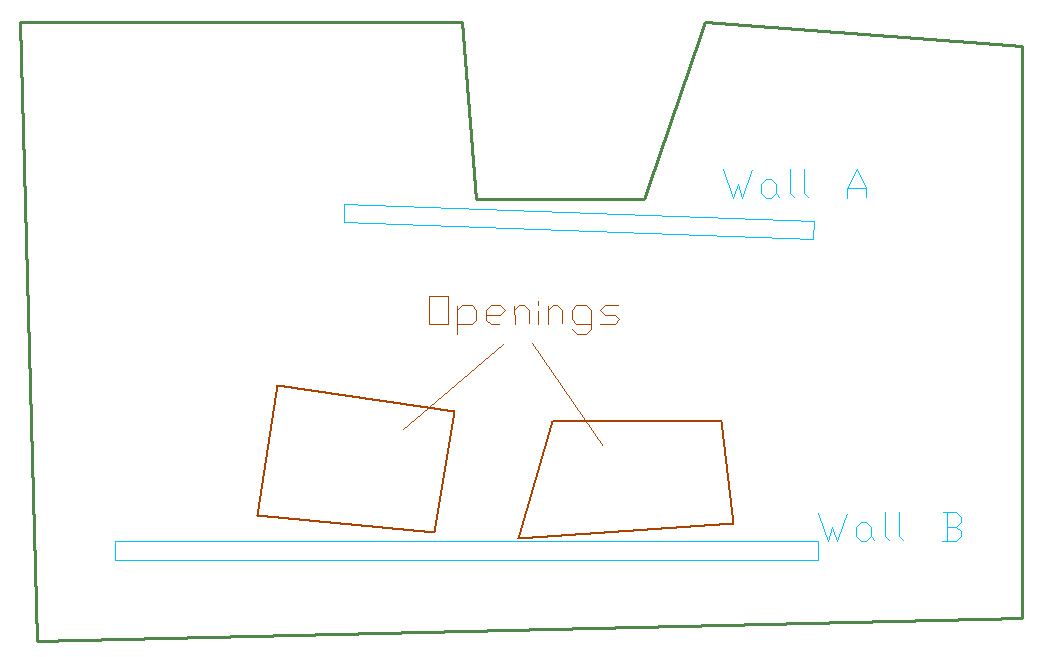
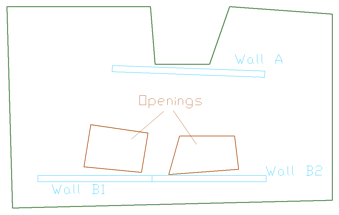
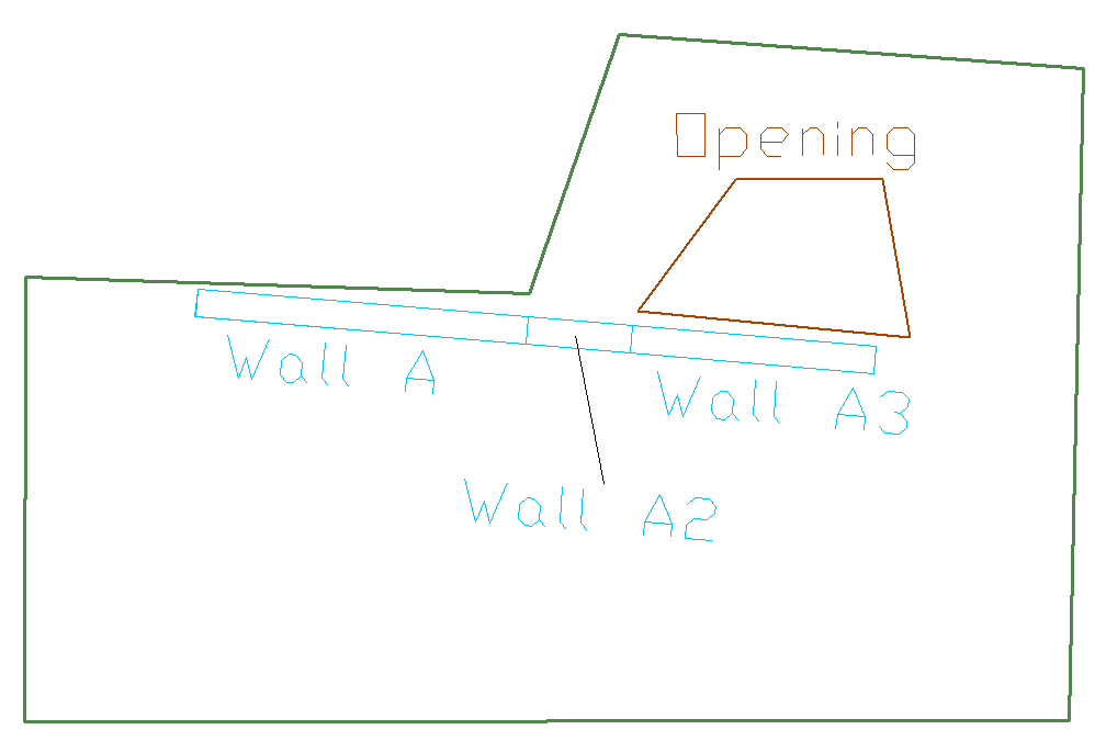
Consider wall A in the image below. This wall need not be subdivided regardless of whether or not shift node option is used, since its analysis axis can be shifted (lined up) to the slab edge next to it. Wall B adjacent to the two openings, however, must be broken down if shift node is used, since its axis cannot be simultaneously lined up with the edges of both of the openings. If node shift option is used, it is best to break up this wall into two segments.
Click image to enlarge
Click image to enlarge
A variation of the above conditions is shown in the below image, where a wall is adjacent to a slab edge and at the same time its extension is close to an opening. Again, it generally is not possible to line up the wall axis with both the slab edge and the edge of the opening. If automatic shift node is to be used, it is best to break the wall into segments as shown in the second image below.
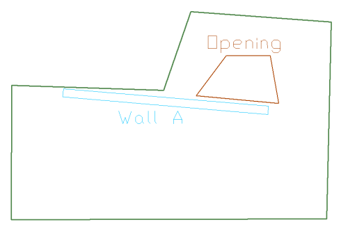
Click image to enlarge
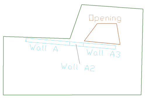
Click image to enlarge


In the Automatic Mesh Generation dialog window, select a suggested maximum cell size 1/6 to 1/8 times the average span.
Select Shift nodes automatically and consider a distance for node shift equal to three times the average slab thickness. A distance between two to four times gives reasonable results.
Disregard sets of components and then mesh. This will help narrow down which component type is causing an issue. Once you find the type of component that causes ADAPT-Mesher to not be able to converge to a mesh, you can start to consider those components in small groups, and then mesh to find the component within that set that is causing the issue. Once the component is found, you can simplify the modeling around that component.
Area’s where the mesh becomes very dense indicate locations where nodes that can not be consolidated are within close proximity to each other. Review the geometry in those locations to see if it can be simplified using any of the techniques previously listed.