The program, by default, will automatically consolidate analysis nodes during the meshing procedure. You also have the option to manually consolidate analysis nodes to locations of your choice. In addition, you can prevent the program from consolidating the nodes automatically when you do not wish nodes to be consolidated.
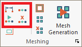
The following sections describe these options in detail. Access the node shifting tools from the Analysis ribbon Meshing panel as shown in the below image.
The tools available here for shifting of nodes are:
The shift node options apply to columns, beams, walls, point supports, and line supports. Once a node is shifted manually, it will remain at its imposed position until you activate the Cancel Node Shift tool. Additionally, you have the ability to Prevent Specific Components From Node Shifting. Before we can use the above tools, it is best to display the component analysis node symbols so we can visualize the change on screen.
To visually see the effects of the consolidation tools on a model, we first need to turn on the symbol for the components' analytical node(s) through the visibility grid.
To display component analysis node symbols:
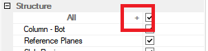
Click on the + icon under the Structure category as displayed below.
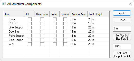
The All Structural Components dialog window will open as shown below.
Click image to enlarge
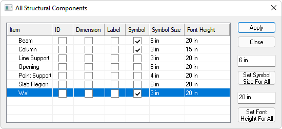
Check the boxes in the symbol column for the walls, columns, and beams as shown below.
Click image to enlarge
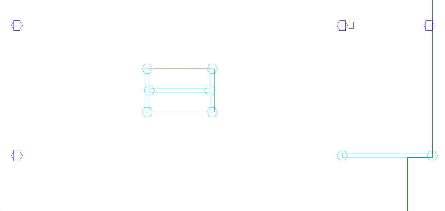
Click the Apply button. You will now see the symbol (hexagon) for the analysis nodes at the ends of walls and beams and at the centroid of the columns, as shown below. Note the symbol size for the components have been increased to 15in in the below figure to exaggerate their size for clear display in the image.

Click image to enlarge
If we zoom in on an area of the slab, we can see the nodes better.
Click image to enlarge
The Node Proximity Detection tool is used to have the program identify nodes within a certain distance from one another, defined by you.
Using the node proximity detection tool:
Go to Analysis>Meshing and click on the Node Proximity Detection tool  icon .
This will open the Node Proximity Detection dialog window.
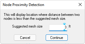
Input the suggested mesh size you plan to use in the Automatic Mesh Generation.
Click on the Continue button.
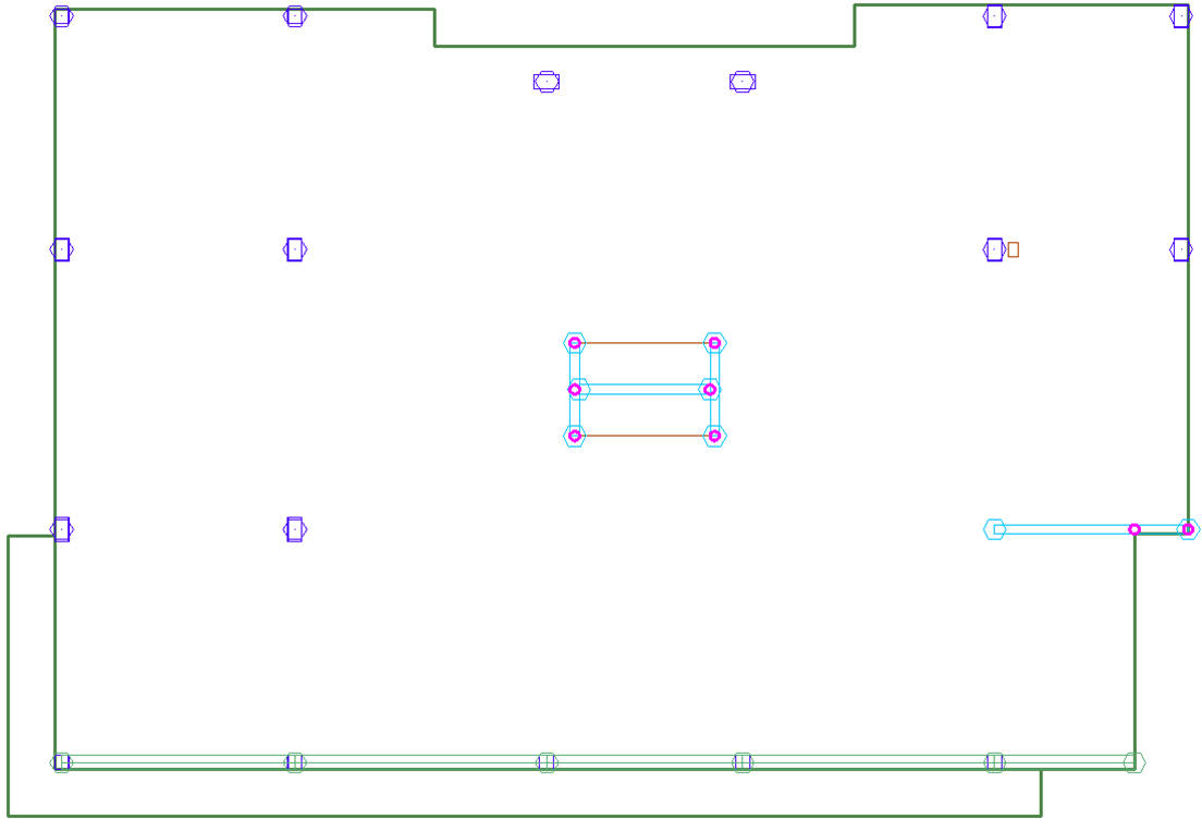
The program will scan your structural model in order to determine whether the details of the structure are such that a cell size will be less than the size suggested by you. If such a location is detected, the program will encircle and display it on the screen as shown in the image below.
Click image to enlarge
We can see the pink circles better when we zoom in on the area as shown below.
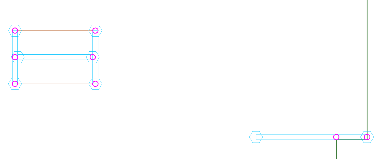
Click image to enlarge
You can then review and modify the circled locations where clean up of the structural model may result in a better mesh.
This tool allows you to have the program automatically shift nodes prior to meshing if we want to see the results of the automatic node shifting.
To shift nodes automatically:
Display the Component Analysis Node Symbols.
A view of a model with nodes at the default locations of components is shown below. Note nodes have been exaggerated for clarity.
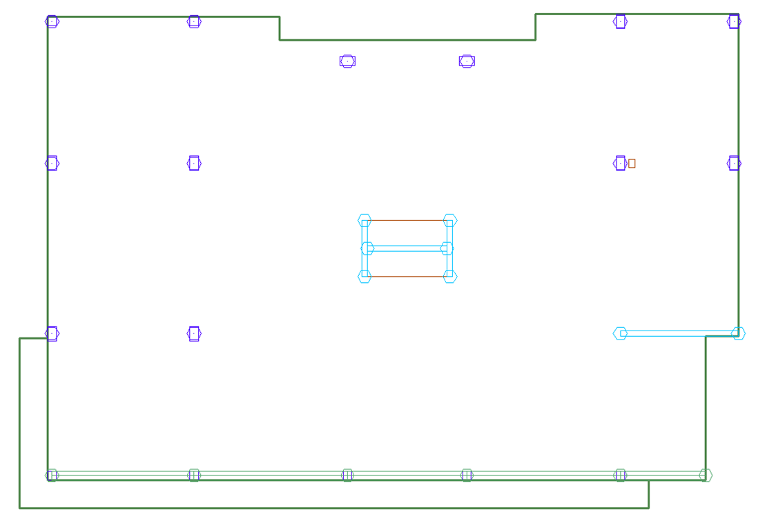
Click image to enlarge
Go to Analysis>Meshing and click on the Shift Nodes Automatically  icon to open the Shift Node Distance dialog window.
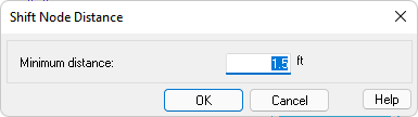
Enter the Maximum Node Shift distance you would like to use.
Click the OK button. The program will shift the nodes of the components to consolidate nodes within the maximum distance provided by you.
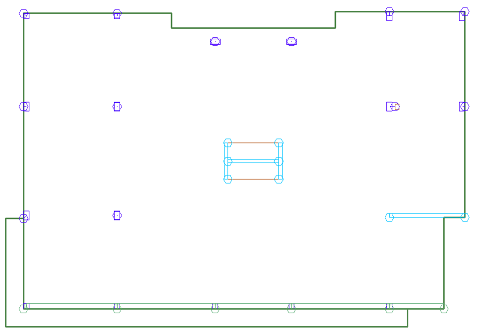
Click image to enlarge
If we zoom in, we can see the node shifting more clearly. Note there are small lines showing the shifting of the analytical node from the component's physical node.
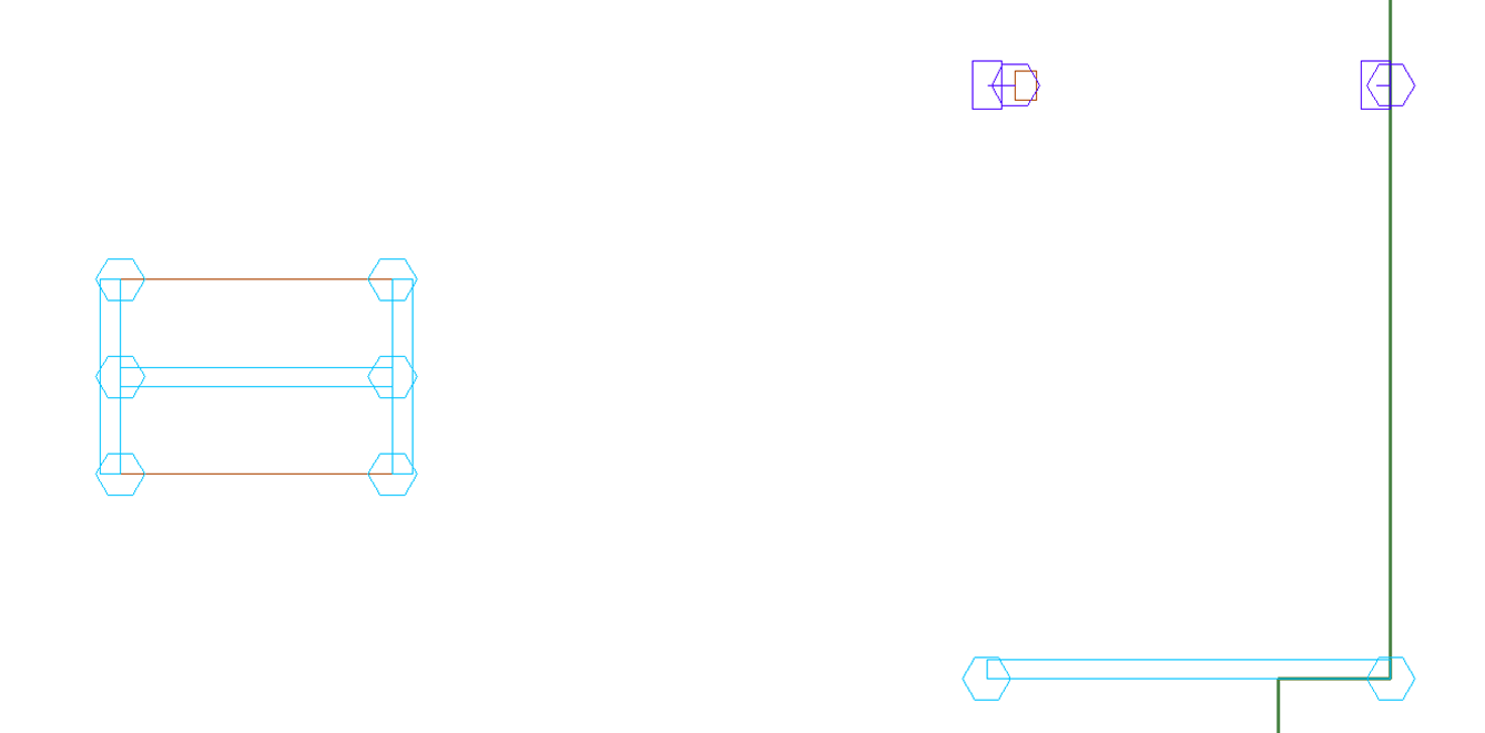
Click image to enlarge
In some cases it may become useful to prevent the model from consolidating nodes of certain components. For example, if you have a small opening with columns on either side of the opening. In this case, you may want to prevent the columns from node shifting to make sure the columns do not consolidate nodes to one side of the opening. In the case you want to prevent a component from node shifting while letting other components node shift, you can follow the below instructions.
To exclude a component from node consolidation:
Select the component or components you want to lock out from node shifting. Note that you must only select one component type (column, wall, beam, drop cap, etc.) at a time.
In the Properties Grid expand the Node Shift tree to expose the Shift Nodes input option.
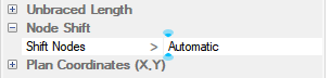
Click on the down caret to expand the drop down list of options. The options consist of Automatic and Manual.
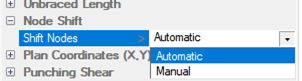
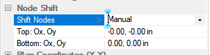
Choose Manual from the list.
The offsets for the components should now appear and be set to 0,0,0 if the node(s) are not being shifted.
You have now locked the component for node shifting. You can use the automatic node shift tool or the node consolidation option during automatic meshing and the components whose node shift option has been set to manual will not be affected.
You have the option to manually consolidate analysis nodes to locations of your choice.
To shift (consolidate) an analysis node manually:
Go to Analysis>Meshing and click on the Shift Node Manually  icon.
icon.
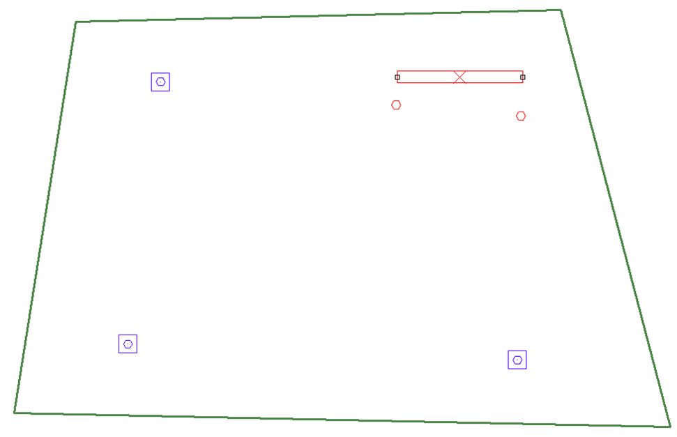
Select the component you want to manually shift the nodes of. In the example below we have selected the wall.
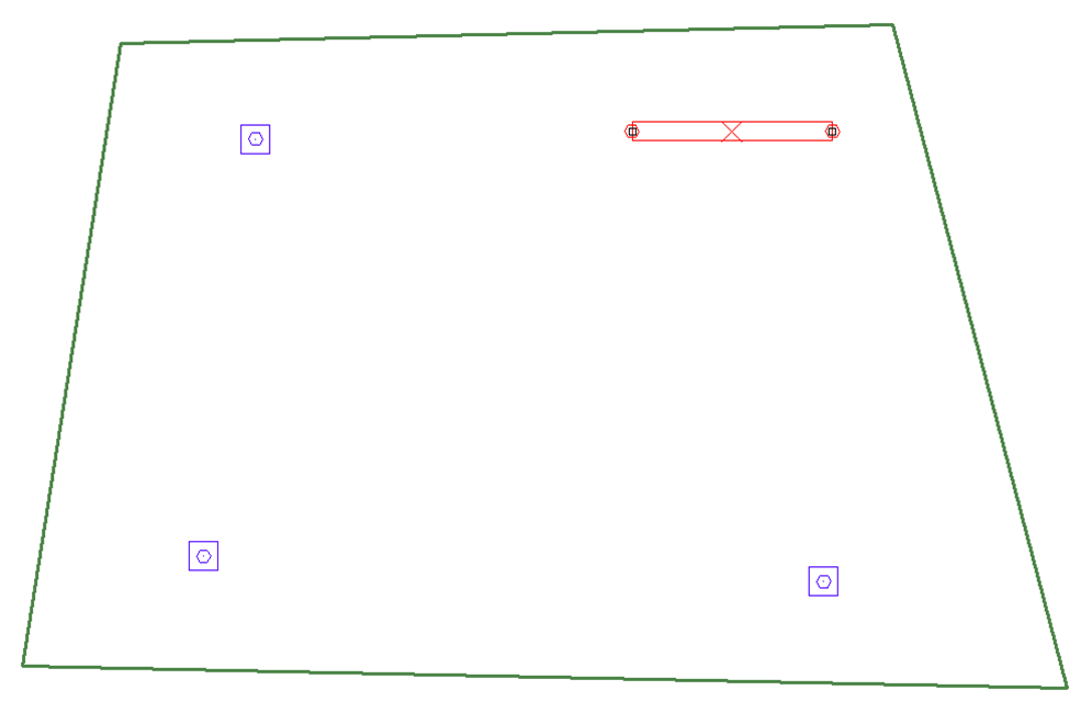
Click image to enlarge
Left click your mouse on the location where you want the 1st node of the wall to be shifted to on plan.
Left click your mouse on the location where you want the 2nd node of the wall to be shifted to on plan.
On plan, if you have the symbols for the component turned on, you will see the symbol for the shifted analysis node as shown in the image below. Refer to the Display Component Analysis Node Symbols section of this topic for more information
 .
.
Click image to enlarge
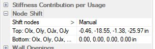
The node shift distance can be seen when the component is selected by expanding the Node Shift section of the Properties Grid as shown below.
The user can repeat the steps for other components in the model.
You can cancel the node shift of all components, or one component at a time, using the Cancel Node Shift  icon in Analysis>Meshing.
To Cancel Node Shifting:
Select the components or component you want to cancel the node shift for. If you want to cancel all node shifting do not select a component and move to step 2.
Go to Analysis>Meshing and click on the Cancel Node Shift icon
Once the operations above are performed, the analytical nodes of the components will be returned to the same location as the physical nodes of the components.


