Click the File ribbon and choose Import.
An Import panel opens.
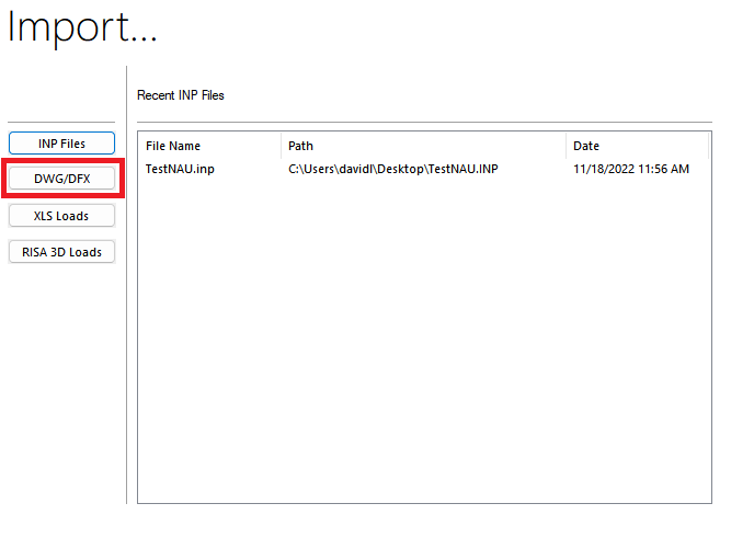
Click on DWG/DFX as shown in the figure above.
An Import a DXF or DWG File window opens.
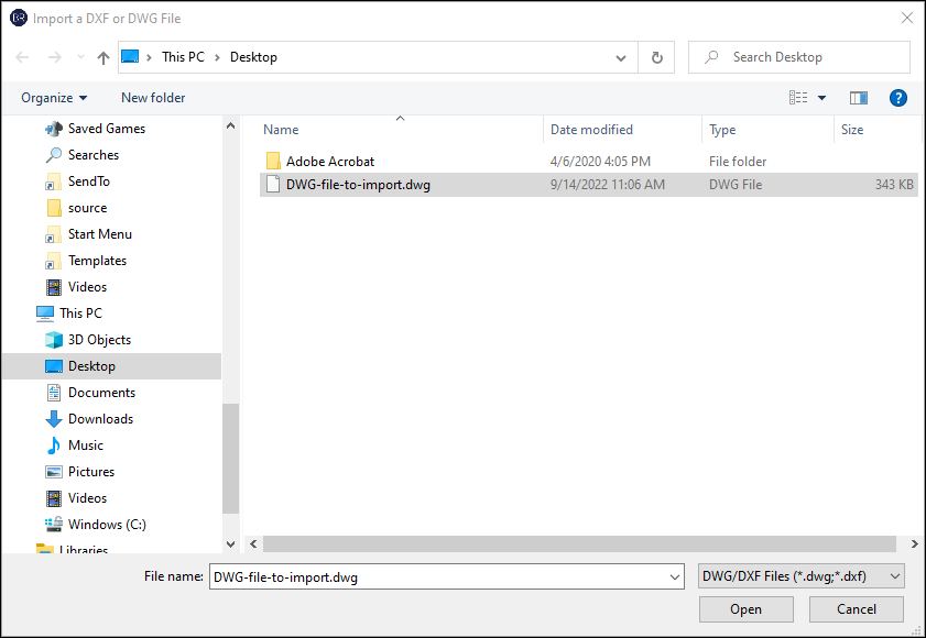
Locate and choose the file to import.
ADAPT-Builder is designed to support the import of CAD files, however, sometimes you may encounter a file with unsupported special objects. If you encounter an error message when trying to import a new Autocad file, we recommend you save it as an earlier 2007 version.
Click Open.
An Import DWG / DXF window opens.
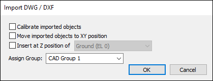
This window allows you to choose between the import options listed in the following table.
| Option | Description |
|---|---|
|
Calibrate imported objects |
Allows you to calibrate the drawing using any of the dimension lines shown in the model. You should check this option for each import. |
|
Move imported objects to XY position |
Allows you to move the imported objects to a specific XY position when other elements are already in the file. Note: The Move Imported Objects to XY position option should be checked if importing to an existing model where the model origin is different than the origin for the coordinates in the DWG/DXF file. The program prompts you to click two points. The first is the base point for the move function, and the second is the end point. Once the end point is entered, the program moves the imported loads to their new position.
|
|
Insert at Z position of |
Allows you to insert the objects on a specific plane in the model. When checked, all objects will be placed on the plane (level) you choose from the drop-down list. |
|
Assign Group |
Allows you to group the imported CAD line work to a specific group. This option is especially useful for multi-level modeling where the floors all have different outlines, as you can assign each imported level to a different group. For example, you can assign the first imported group to Level 1, the second to Level 2, and so on. You can either choose an existing group from the drop-down list or type in a new group name in the Assign Group box. These groups can then be displayed (on/off), purged, or deleted, using the Group Library icon From Visibility > Display Settings. |
Check the object options you want.
-
When importing for the first time into a new file, you’ll only need to check the Calibrate imported objects checkbox.
-
When importing into an existing file or into a new file after the initial import, you’ll want to check the Calibrate imported objects checkbox and the Move imported objects to XY position checkbox, so that you can reposition the additional imported objects as needed.
Note: You may find it helpful to assign each imported level its own Group or Z level. Therefore, if multiple levels have the same DWG/DFX file, and hence the same layer naming convention, you can name each as such (i.e., Levels 3-7, etc).
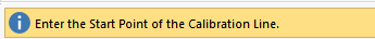
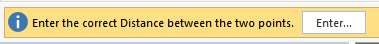
Click the Enter button in the User Message Bar (UMB).
A Drawing Input window opens.
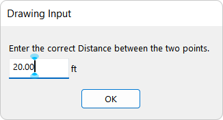
In the ft box, type the correct distance in feet between the two points you entered on plan and then click OK.