The Support Line Dynamic Editor includes tools you can use to more efficiently create, modify and customize support lines and design strips. It includes the ability to auto-generate middle strips for use in either RC or PT mode.
This Support Line Dynamic Editor is found at Floor Design > Strip Modeling. Manual creation of support lines is still available through the use of the Create X and Create Y Support Line tools.
The image below shows the Dynamic Editor window. Note the option is given to ‘Pause’ or ‘Resume.’ This allows you to keep the window open if needed, while you work in the main User Interface.
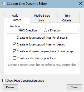
The Dynamic Editor contains six tabs; Wizard, Limits, Criteria, Walls, Middle Strips and Trim. Each of these are described in the following sections. The Show/Hide Construction Lines checkbox lets you choose whether or not to show the lines in the model you are working with.
The Wizard tab allows you to create a support based on a construction line defined by snap points along the strip path.
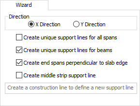
The following table provides descriptions of the options available when using the Wizard to create support lines.
| Option | Description |
|---|---|
|
Direction |
Direction allows you to the direction for the support line. Choices are:
Support lines tagged as X-Direction or Y-Direction do not necessarily need to be drawn in these directions. The direction is used when you need to add support lines in two directions, as a support line cannot intersect a support line tagged with the same direction. |
|
Create unique support lines for all spans |
When checked, the program breaks up a continuous support line into separate support lines for each span (between each support the construction line passes through). In the image below, you can see that the program created six unique regions.
Click on image to enlarge it This option can be useful in combination with the new tools for allocation of column strip percentage, so that you can assign different values in each span versus the same column strip allocation over a continuous, multi-span condition. When not checked, the program creates a continuous support line and strip, as shown in the following two images.
Click on image to enlarge it
Click on image to enlarge it |
|
Create unique support lines for beams |
When checked, breaks the support line into three different support lines, when the user clicks within the beam end points while creating the construction line. The program will create a support line for the slab prior to the beam, a support line from the start to end of the beam, and one support line after the beam. The program will assign the support lines in the slab with Two-Way design criteria and the support line within the beam will be tagged with Beam design criteria.
Click on image to enlarge it |
|
Create end spans perpendicular to slab edge |
When checked, the program aligns the ends of support lines to be perpendicular to the slab edge. When the construction line is used to create a support line through use of the wizard, it is not practical to align the construction line perpendicular with the slab edge, nor are the snap tools active when drawing a construction line. See examples below.
Click on image to enlarge it
Click on image to enlarge it When not checked, the support line follows the construction line vector.
Click on image to enlarge it |
|
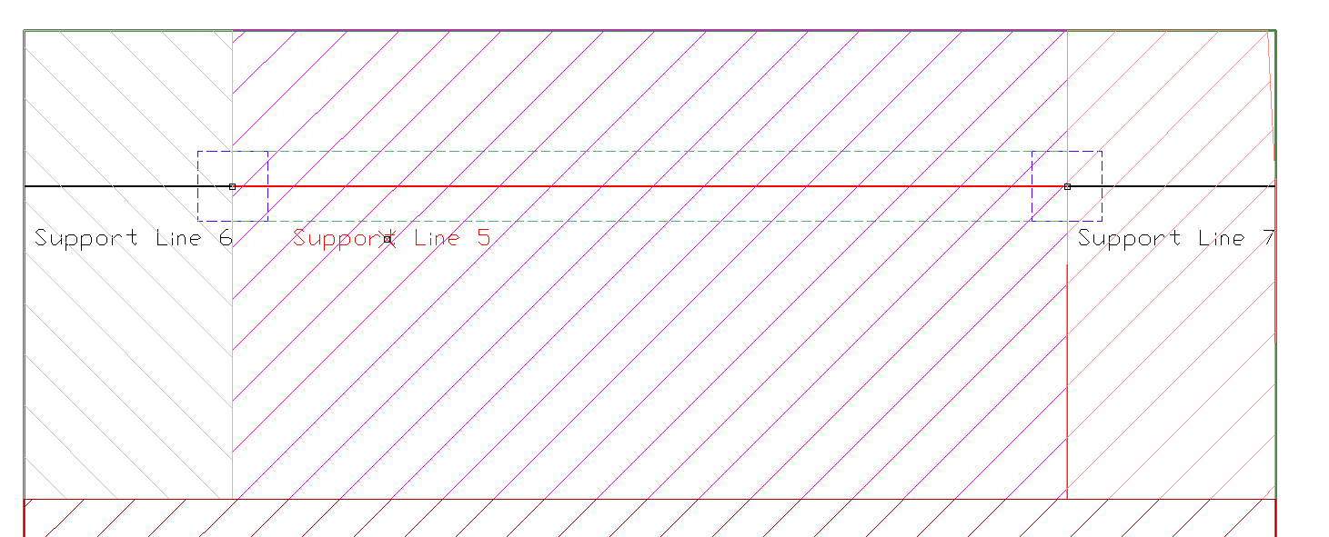
When checked, the program automatically tags a support line as “Middle Strip” in the Property Grid as shown in the following image. This tag is especially important in how tributary regions are created by the program.
When a support line is tagged as “Middle Strip” the tributary boundary extends to the column strip boundary regardless of whether the column strip has a boundary setting as None, % distance, or max limit. See the following cases for examples and explanations.
Click on image to enlarge it The typical bay width and length is 30’ x 30’. In this case the column strip is automatically ½ the distance to the adjacent support line and the middle strip is ½ the distance each side to the adjacent support line. This results in the column strip within the bay being 1/4 *bay width and the middle strip being ½*bay width.
Click on image to enlarge it In this condition the support line representing the middle strip support line but not tagged as MIDDLE STRIP is limited to ½ the distance (15’ in this case) to the adjacent support line. The column strips are extended 0.15*distance to each side of the support line to the next support line. For this case, the distance between support lines is 15’. The column strip distance is therefore 0.15*15 = 2.09’ each side of the support line representing the column strip.
Click on image to enlarge it In this condition the support line representing the middle strip support line but not tagged as MIDDLE STRIP is limited to ½ the distance to the adjacent support line (15’ in this case). The column strips are extended to the direct input for the max width of 4.5’.
Click on image to enlarge it In this condition the support line representing the middle strip support line tagged as MIDDLE STRIP fills in the gap relative to the rule set for the column strip support line. For this case, the column strip is automatically generated as ½ the distance to the adjacent support line on each side. Therefore, the length is 7.5’ for the column strips to each side of the support line and the middle strip is 15’.
Click on image to enlarge it In this condition the support line representing the middle strip support line tagged as MIDDLE STRIP fills in the gap relative to the rule set for the column strip support line. For this case, the column strip is set to a % difference between support lines of 15%. This leads to the column strip width being set as 4.5’ each side of the support line and the middle strip filling in the gap at 21’.
Click on image to enlarge it In this condition the support line representing the middle strip support line tagged as MIDDLE STRIP fills in the gap relative to the rule set for the column strip support line. For this case, the column strip is set to a percent between of 15%. This leads to the column strip width being set as 4.5’ each side of the support line and the middle strip filling in the gap at 21’. Note at the column strip support line at the top edge of the slab a gap exists between the strip boundary and edge of slab. This is caused due to the setting of max width of 4.5’ of each side. The cantilevered distance is greater than 4.5’. |
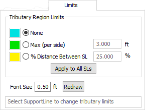
The (Tributary Region) Limits tab allows you to change the selected support line design criteria and tributary limits for the design strip. When this tab is selected, the current design criteria and limits are displayed on all support lines. Set the desired criteria and snap or window support lines to modify to the desired setting.
The six cases under Create middle strip support line in the previous section describe all conditions and settings for the Limits option. These settings are typically applied to only those support lines representing column strips. Middle strip creation is handled separately through manual definition and tagging as a “Middle Strip”, or through the use of the Middle Strips tab. In other words, middle strips are commonly set as 'None' for tributary region limits.
The following table provides descriptions of the options available when using the Wizard to create support lines.
| Option | Description |
|---|---|
|
Tributary Region Limits |
Tributary Region Limits allows you to change the selected support line design criteria and tributary limits for the design strip. There are three options from which you can choose:
|
|
Apply to All SLs |
When the Apply to All SLs button is clicked, the program sets the tributary region limit to each support line modeled in both X and Y directions. If you select only a single support line, the program changes only that support line. |
|
Font Size |
The Font Size options allows you to set the font size for the text showing the tributary region limit setting in the model. The following example shows a mixed set of support lines with different limit conditions. Note that the colorized indication is only active while in the Dynamic Support Line Editor. Example: Mixed support lines with different limits
Click on image to enlarge it |
|
Redraw |
The Redraw button updates the text size in the mode when you change the size. You must click Redraw in order to see the size change in the model. |
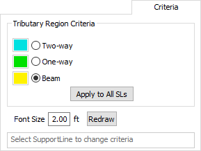
The (Tributary Region) Criteria tab allows you to assign how the selected support line is treated for design criteria. Design criteria is used by the design algorithm to determine how minimum reinforcement, strength reinforcement, shear requirements, flexural stresses, etc., are handled.
The following table provides descriptions of the options available when using the Wizard to create support lines.
| Option | Description |
|---|---|
| Two-way | When chosen, the program sets the design criteria as two-way slab. If tendons intersect the design section, two-way PT criteria is used, otherwise RC criteria is used. Allowable stress input, reinforcement size and bar cover is dependent on this setting. Two-way criteria is represented by Cyan support lines. |
| One-way | When chosen, the program sets the design criteria as one-way slab. If tendons intersect the design section, one-way PT criteria is used, otherwise RC criteria is used. Allowable stress input, reinforcement size and bar cover is dependent on this setting. One-way criteria is represented by Green support lines. |
| Beam | When chosen, the program sets the design criteria as beam. If tendons intersect the design section PT beam criteria is used, otherwise RC criteria is used. Allowable stress input, reinforcement size and bar cover is dependent on this setting. Beam criteria is represented by Yellow support lines. |
| Apply to All SLs |
When the Apply to All SLs button is clicked, the program sets the criteria type to each support line modeled in both X and Y directions. If you select only a single support line, the program will change only that support line. |
|
Font Size |
The Font Size options allows you to set the font size for the text showing the tributary region limit setting. The image below shows an example of a mixed set of support lines with different Criteria settings. Note that the colorized indication is only active while in the Dynamic Support Line Editor. Example: Mixed support lines with different limits
Click on image to enlarge it |
The Walls tab allows you to set boundary conditions for how walls are considered for design strip tributary generation. The default conditions are set to automatically consider walls as X and Y boundaries. Options are given for you to manually define how walls are treated, using a User Def (define) set of boundary options.
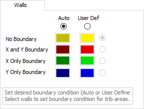
When you set User-defined boundaries, those boundaries remain until you set the option back to ‘Auto’ or until you change the manual boundary set to another option. The following link contains an instructional video that illustrates more detailed use of wall boundaries.
https://www.youtube.com/watch?v=vbY5_tec9vo
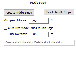
The Middle Strips tab allows you to set, create, or delete middle strips. When you create middle strips, you can also choose whether to automatically trim them to the slab edge.
The following table provides descriptions of the options available when using the Wizard to create middle strip support lines.
| Option | Description |
|---|---|
| Create Middle Strips |
When the Create Middle Strips button is clicked, the program automatically generates middle strip support lines between already-defined column strip support lines. These lines are colored in blue, while active in the Support Line Dynamic Editor.
Click on image to enlarge it |
| Delete Middle Strips | When the Delete Middle Strips button is clicked, the program removes the auto-generated middle strip support lines. |
| Min Span Distance | This options allows you to set the threshold for the minimum span distance of a column strip support line, that the program uses to generate a middle strip. |
| Auto Trim Middle Strip to Slab Edge | When chosen, the program auto trims/extends the ends of the middle strips to the slab edge located in the tolerance setting. |
The Trim tab allows you to trim the ends of support lines at the slab edges or openings, if the end is within the tolerance setting.
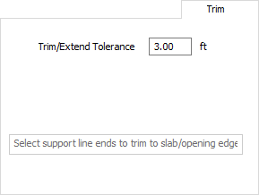
Select the endpoint of the support line to trim or extend.