Effective Flange Width
The program includes the option to calculate the effective flange and properties of beams when the support line is snapped to a beam component. The design of the beam sections is performed using the effective properties. The component of stress related to the precompression uses the full tributary area of the section as does the graphical precompression result. ACI and EC2 calculations for effective width are supported.
When the effective flange option is used, the program uses effective properties in performing the following calculations:
-
Calculation of reinforcement for minimum service reinforcement and strength reinforcement requirements of the design section
-
Calculation of flexural stresses for PT design sections. The component of the stress calculation, My/I, is based on the centroid of the effective section and moment of inertia of the effective section. The component of the stress calculation, P/A, uses the area based on the full design section as modeled for the design strip. Note that the P/A as reported graphically is based on the full tributary area, not the effective area.
Actions for the design of effective sections are those as calculated per the Nodal Integration Method over the full tributary width of the design section.
Please see Technical Note TN302 - Evaluation of Design Values at Design Sections for more information. Please see the Methodology section of this topic for more information.
To define the effective flange option:
-
Select the support line you want to apply the effective flange width option to.
-
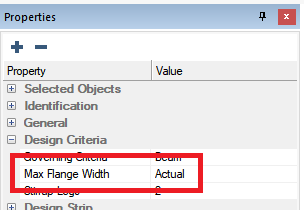
In the Properties Grid expand the Design Criteria tree and locate the Max Flange Width input option.
-
Click in the Max Flange Width cell in the Value column to expand the options you can choose.
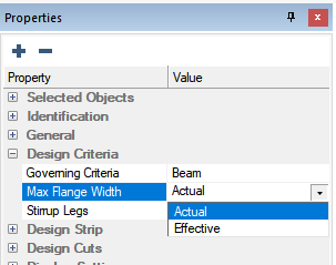
-
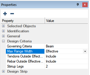
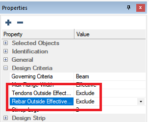
Choose the Effective Width option.
-
Two additional options to include or exclude tendons and rebar outside of the effective flange become available. If these options are set to Exclude, the program will ignore the area of prestressing steel or mild reinforcement that fall within the modeled tributary but outside effective flange, for calculation of reinforcement for the design section.
-
Go to Floor Design> Section Design and click on the Generate Sections  icon.
icon.
-
Go to Floor Design> Section Design and click on the Design the Sections  icon.
icon.
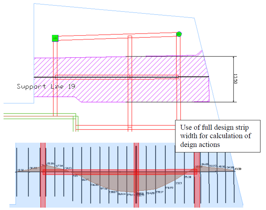
Note for the image below, the generated design strip is taken as the full tributary of 13.5 ft (162 in). The design actions reported at each design section along the support line are based on nodal integration of the actions over the full width of the generated design strip.
Click on image to enlarge it
-
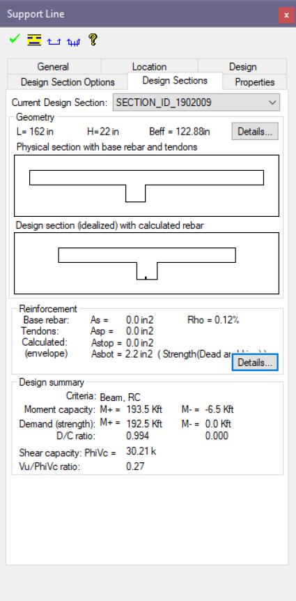
Double click on a design section to bring up the design section window. The image below shows the properties of a design section with consideration of effective flange properties. While the generated design strip width is 162in., the effective flange width as used in the calculation of reinforcement and flexural stress is taken and calculated as 122.9in. The window below shows two images. The first is the physical section cut and the second is the idealized section cut which uses the effective flange.
Click on image to enlarge it
Methodology
The program includes effective flange formulation for three design codes: ACI 318-14, ACI 318-19, and EC2. All design codes will default to the ACI methodology expect for EC2 and NBR codes. You can also manually generate splitters or use max tributary offset input for the design strip to manually define flange widths.
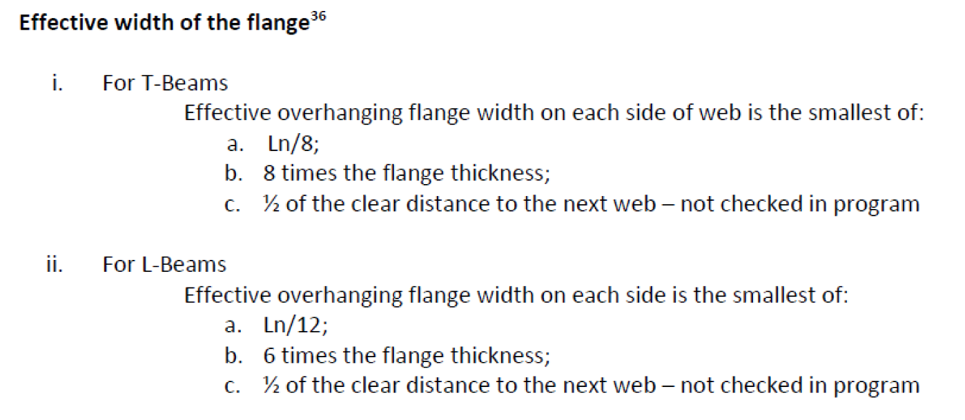
The implementation for ACI uses the following expressions from ACI 318-14 Section 6.3.2, excluding point (c).
Click on image to enlarge it
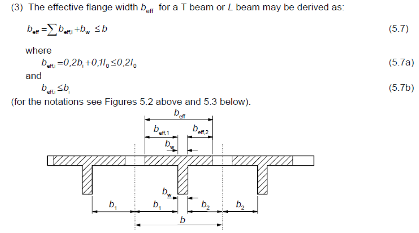
The implementation for EC2 uses the following expressions from EN 1992-1-1:2004 Section 5.3.2.1 (3).
Click on image to enlarge it