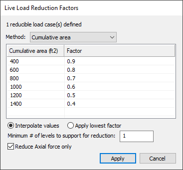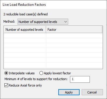
The Live Load Reduction Factors window allows you to modify the reduction method, area and factors settings to be applied to load cases tagged as Reducible in the Load Case Manager.

The reduction factor calculation depends on the creation of tributary regions from Loading>Load Takedown. Load Reduction Factors are applied in only two ways:
Column Design - If the Load Reduction setting in (Column) Design Options is set to 'Yes', the reduced loads will be applied for column design. The Load Reduction setting can be found by going to 'Column Design', Design Settings - under Design Parameters.
Analysis of Single-Level - If a Multi-Level analysis has been performed, reactions can be re-applied in Single-Level mode with inclusion of load takedown (Fz reactions). Go to 'Analysis', 'Analysis Options' and check (select) the Apply live load reduction option.
Live load values specified in the code are determined statistically, using a notional floor area. For floor areas larger than the notional areas used in the building codes, there is less of a likelihood of the load covering the entire area with the code-specified intensity. For this reason, the building codes generally allow a reduction in the intensity of the specified live load, when the load covers large areas.
ADAPT-Floor Pro and ADAPT-MAT can automatically determine the reduction in intensity of the live load specified, and accounts for it in its analysis. It also reports the reduction value used. An additional option allows you to enter reduction values. Note that the reduction of live load for analysis is an option that you must select in your input data. Otherwise, the program applies the entire load you have specified over the area you selected.
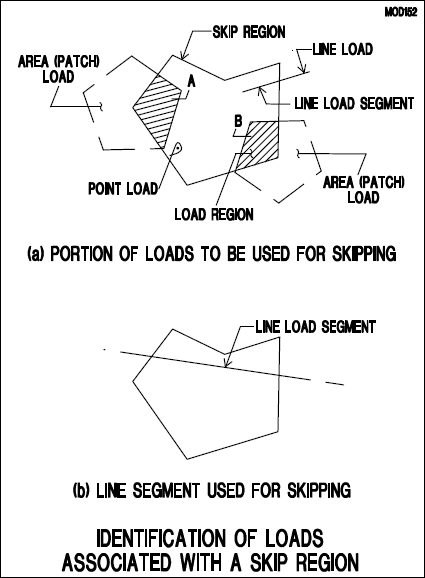
When using live load reduction in conjunction with pattern loading the value of the factor used for the reduction of live load is calculated for each skip region (see the preceding section for the definition of skip regions). Hence, each skip region has its own coefficient of live load reduction. The area used for the calculation of the live load reduction in each skip region is strictly the area covered by the live load in that region. This is shown graphically by the hatched regions in the following figure.

The concentrated (point) loads and the line loads that are part of the live load being reduced, and that fall within the skip region under consideration, are not reduced. The reduction is applied only to the distributed loads.
If you do not define a skip region, the program applies the reduction to the entire area of each part of the live load you have defined. For the reduction of live load, the program uses the recommendations of the IBC-2005 (International Building Code), as detailed below:
R = 0.08(A – 150)
Where:
R = reduction factor, not to exceed 40%; and
A = tributary in square feet (where the live load is applied.)
Nor more than
R = 23.1 (1 + D/L0) = < 40%
Where:
D = the dead load, and
L0 = the applicable live load
To apply the factors for live load reduction:
Click on the Loading ribbon.
Click the LLR Reduction Settings icon in the LL Reduction panel, to open the Live Load Reduction Factors window.

In this window you define the cumulative tributary region area and load factor applied to that cumulative area. The program then assigns these factors to live load reactions for columns when the columns are designed. Note that you can choose not to apply the factors.
Choose a method to use; Cumulative area or Number of supported levels.

Modify the Cumulative Area or # of Levels and the Factor input values.

(Optional) To add a new entry for area and factor:
Right-click on a blank row to open an options menu.
Click on Append.
Click on the cell you want to modify, to highlight it.
Type the new input in its place.
(Optional) To modify the cumulative area, number of levels or factor value:
Click on the cell you want to modify, to highlight it.
Type the new factor in its place.
Choose either Interpolate values or Apply lowest factor, depending on the method to use.
Type in a Minimum # of level to support for reduction in the text box.
Click Apply.
(Optional) To see the results of your choices (only available if load takedown tributaries have been generated):
Open the Results View panel ('Analysis', 'Results Display Settings').
Choose the Analysis tab.
Expand the Load Takedown tree.
Click on Load Reduction Factor.
The model is refreshed to display all the load reduction factors.

(Optional) To add a new entry for supported levels and factor:
Right-click on the empty row to open an options menu.
Click on Append.
Enter the values for the new row.
(Optional) To modify the factor value of a Number of supported levels:
Click on the factor you want to change, to highlight it.
Type the new factor in its place.
Choose either Interpolate values or Apply lowest factor, depending on which you want to do.
Type in a Minimum # of level to support for reduction in the text box.
Click Apply.
(Optional) To see the results of your choices:
Open the Results View panel ('Analysis', 'Results Display Settings').
Choose the Analysis tab.
Expand the Load Takedown tree.
Click on Load Reduction Factor.
The model is refreshed to display all the load reduction factors.
For applications of the live load reduction settings in the analysis and design of components click here to see a video.