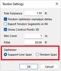
ADAPT-Builder includes a Support Line Span Optimizer that allows the user to optimize tendons within a support line span based on stress, precompression, and balanced loading percentages. The Support Line Span optimizer will optimize tendons based on the FEM results from the envelope of service combinations analyzed. The initial combination is not included in the optimization as the program will add reinforcement per code when tension stresses are exceeded for the initial combination. Once the tendons have been optimized the user has the choice to Update the Service Solution to see the effect the change has on the FEM analysis and design, or continue to optimize tendons in other support line spans whose tendons have not been modified by the optimizer. By default the Support Line Span Optimizer is located on the Tendon ribbon.
Click on image to enlarge it
Access the Support Line Span Optimizer from the Tendon ribbon Optimizers panel Support Line Span icon.

To optimize a support line span:
Click on the Support Line Span  icon to open the PT Strip Optimizer dialog window.
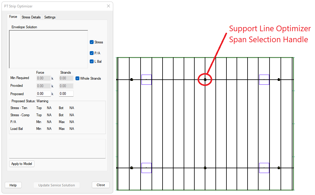
When the Support Line Span optimizer opens, the program will show "handles" along all visible support lines. Window select a "handle" to select a span along a support line to optimize.
Click on image to enlarge it
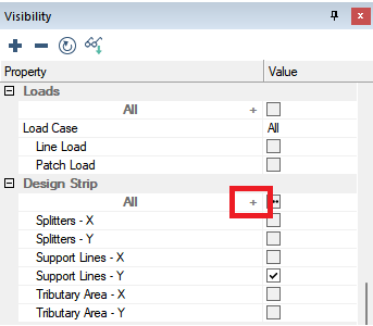
The handle size can be increased or decreased by clicking the + sign in the Design Strip category of the Visibility panel.
Click on image to enlarge it
This will open the All Design Strip Components window where you can increase or decrease the Symbol Size parameter for the support lines as shown below.
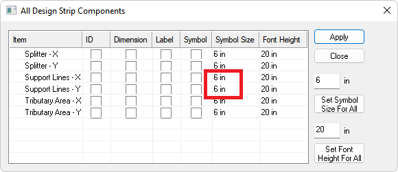
Click on image to enlarge it
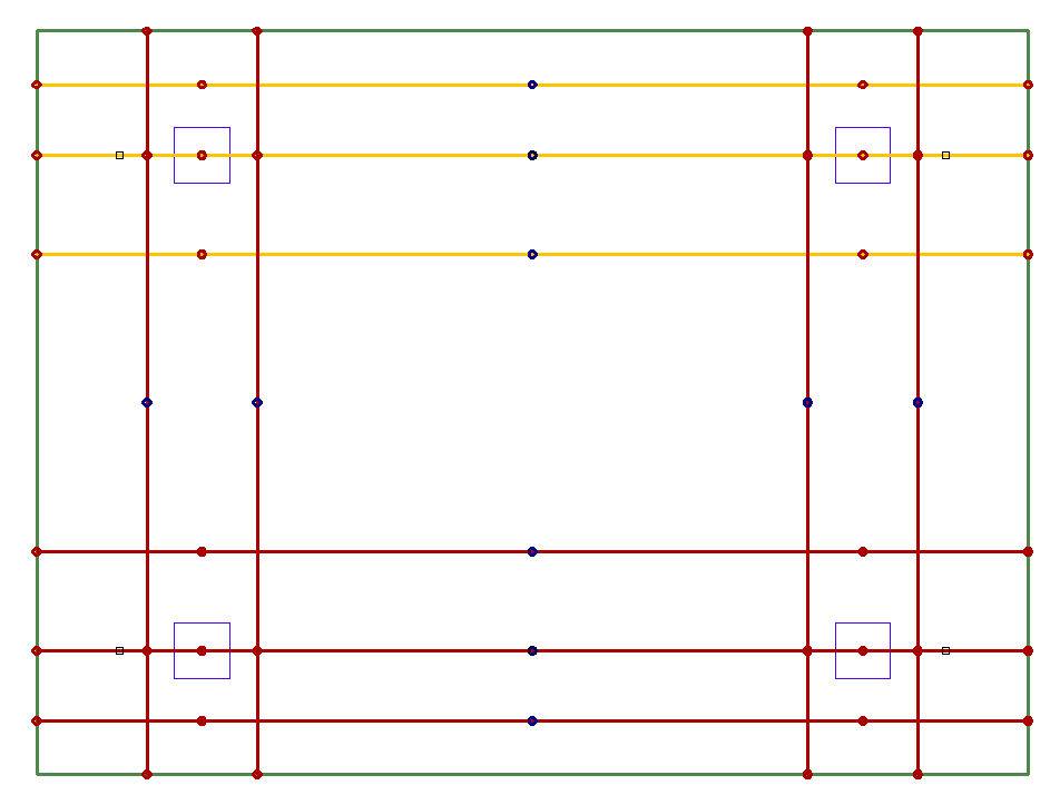
Once the span is selected the program will show three cyan design sections to be optimized. Each highlighted section is labeled A, B or C. The design sections will be chosen at the ends and the middle of the span. You have the ability to choose different design sections than those chosen by the support line span optimizer through the Settings tab of the PT Strip Optimizer dialog. The program will also label the tendons found by the optimizer and list the force, number of strands, and CGS of the tendons in blue text.
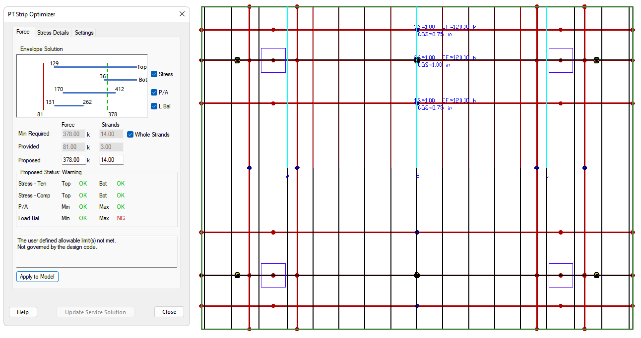
Click on image to enlarge it
If the proposed force is acceptable click on the Apply to Model button to apply the change in number of strands to the tendons.
Once the number of strands change has been applied to the tendons you can select another span to optimize, update the service solution, or close the optimizer and update the entire solution.
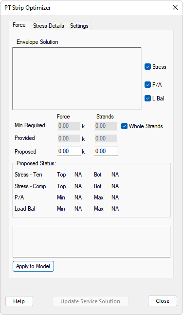
The PT Strip Optimizer dialog contains three tabs; Force, Stress Details and Settings. Each of these are described in detail in the following sections.
This section describes in detail the options of the Support Line Span Optimizer - Force Tab. For information on the general use of the Support Line Span Optimizer please refer to the beginning of the Support Line Span Optimizer topic.
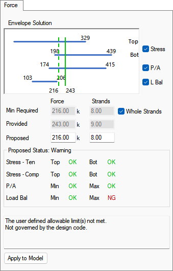
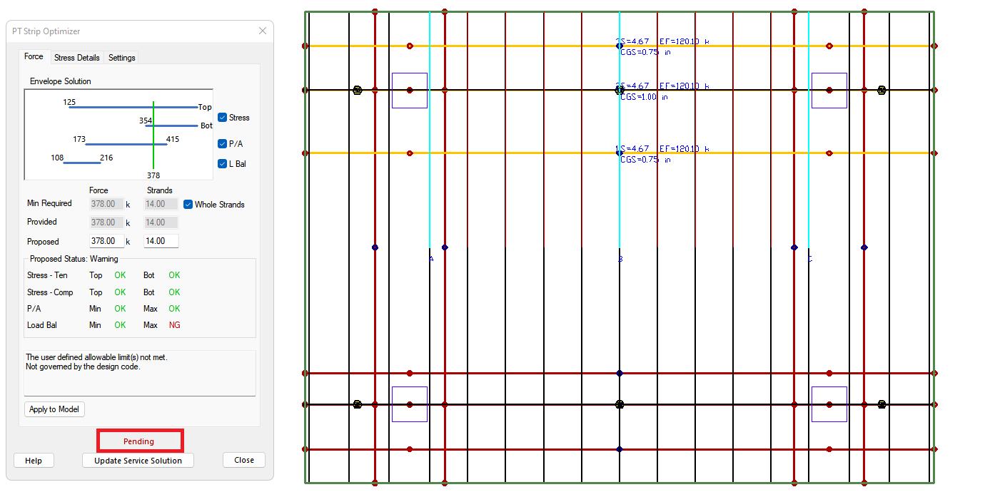
The Force tab of the tendon optimizer includes the Optimization Diagram, the Min Required, Provided, and Proposed tendon forces, as well as the Proposed Force Status and Message box sections. Lastly the Force tab gives the option to Apply to Model, the proposed force, to the tendons within the strip.
Optimization Diagram
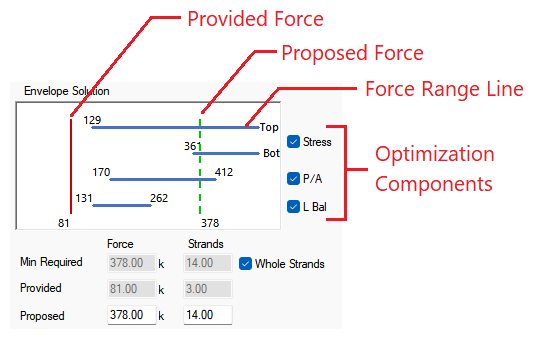
The optimization diagram represents the outcome of calculations. It displays the Force Range Lines and Provided and Proposed forces lines.
Click on image to enlarge it
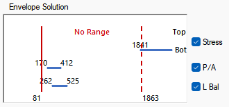
The Force Range lines represent the post-tensioning force values that satisfy allowable values for all load combinations at the three optimizer design sections at the same time for each optimization component (Top and Bottom Stress, P/A, L Bal). Unchecking the check box for a component disables that component and will not include that component in the optimization of tendons. If the component is checked and a valid range exists the program will draw a range line as a solid blue horizontal line and show the min/max force values that solve that components allowable limits at the start and end of the force range lines. If the component is checked and the range value does not exist the program will show a red No Range text to alert you that there is no force range that satisfies the allowable criteria for the component. Typically if No Range is shown a geometry or loading change is needed. An example of the No Range text is shown below.
Click on image to enlarge it
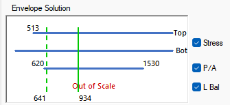
If the component checked requires an infinitely large force to satisfy the program will show a red Out of Scale text to alert the user. An example of this is when you have a profile that has no uplift and very low Lbal percentages the program will require an infinite amount of force to solve for the balanced loading allowable range. An example of the Out of Scale text is shown below.
Click on image to enlarge it
The Provided Force is represented by a solid red or green vertical line, the color depends on if the force falls within the allowable range for all checked components for all combinations. If the line is green all components of optimization are satisfied, while a red color means some component is outside of the allowable range. The provided force value is shown at the bottom of the provided force line. The provided force is the equivalent force calculated based on the total number of strands and average effective force for “active” tendons. “Active” tendons are tendons selected by the program for optimization. The tendons must cut all three optimizer sections and have an angle less than 30 degrees with respect to the support line to be considered "active" by the optimizer.
The Proposed Force is represented by a dashed red or green line. The color of the proposed force line depends on if the proposed force solves all the checked components for all sections and combinations. The proposed force value is shown at the bottom of the proposed force line. The proposed force is equal to the Min. Required force calculated by the program to solve for all components of the optimization that are included. The proposed force can be overwritten by you. Once the proposed force is overwritten click on a different input box to update the Optimization diagram.
The Min. Required Force is the smallest tendon force that is calculated by the program to satisfy all selected allowable limits. If the program cannot satisfy all limits than the order of preference is as follows:
Tension stress (top and bottom)
Minimum P/A (precompression)
Minimum %Wbal (load balancing)
Located in the Force Tab is a Whole Strands check box. Checking this box limits the force change to that of whole strand numbers for the Min. Required Force. The Proposed Force is a user input that can be in decimal format even when the Whole Strands option is active. Unchecking the whole strands check box allows the program to use decimal numbers for strands to dial in on the minimum force needed to optimize the tendons.
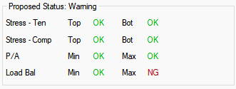
Status Display
The program reports the status only for the Proposed force.
Click on image to enlarge it
The Status Display section shows the status check for each optimized component. The Proposed Status gives the overall status of the proposed force optimization. The Proposed Status can be set to:
Fail - Status fails when the either the stress or minimum precompression is exceeded.
Warning - Status is set to warning when stress and minimum precompression are within allowable limits and one of either the max P/A or min/max Load Bal checks exceed the user set allowable limit.
Pass - Status is set to pass when the calculated value is within the allowable range for all components being optimized.
Below the proposed force status the program lists the Calculated vs. Allowable checks done for each component and each limit. The calculated force is checked against the allowable and a status is presented. The outcome is one of the following:
NA - if component is not selected (unchecked)
NG - if calculated value is falls outside the allowable limits
OK - if calculated value is within the allowable limits
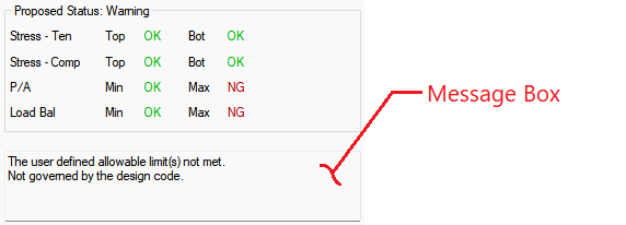
Message Box
The Message Box is located below the Status Display section of the Force tab. The message box outputs messages in the case where there is a warning in the Proposed Status.
Click on image to enlarge it
This section describes in detail the options of the Apply Options dialog. For information on the general use of the Support Line Span Optimizer please refer to the beginning of the Support Line Span Optimizer topic.
The Apply to Model button modifies the tendons to increase or decrease the provided force found in the sections to equal the proposed force. Clicking the apply to model button opens the Apply Options dialog window shown below.
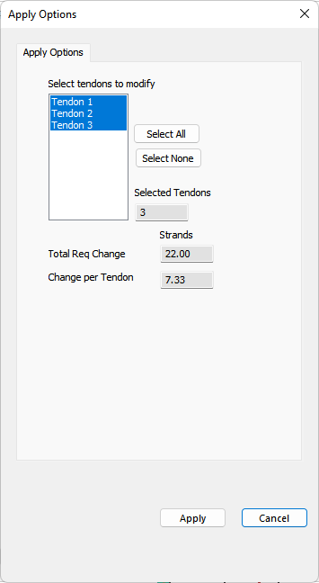
The user can select the tendons listed in the Select Tendons to Modify list to apply the changes to. Selected tendons are highlighted with a blue color. The Select All button will select all listed tendons while the Select None button will deselect all listed tendons. As you select or deselect tendons the remaining text boxes will update. The Selected Tendons text box shows the number of tendons selected. The Total Req Change text box lists the total number of strands being added to or removed from the selected tendons. The Change per Tendon text box lists the number of strands being added or removed from each selected tendon.
Clicking the Apply button applies the change to the number of strands to the selected tendons. Once the changes have been applied to the tendons the user will be brought back to the Force tab of the PT Strip Optimizer dialog window and the modified tendons will be shown in an orange color. Once tendons have been modified by the optimizer, you will no longer be able to optimize any support line span that cuts an already optimized tendon until the solution has been updated using the Update Service Solution button or by doing a complete analysis and design.
Clicking the Cancel button cancels the Apply to Model function and brings the user back to the PT Strip Optimizer window.
This section describes in detail the options of the Support Line Span Optimizer - Stress Details tab. For information on the general use of the Support Line Span Optimizer please refer to the beginning of the Support Line Span Optimizer topic.
The Stress Details tab allows the user to review the stresses at each optimizer design section for each load combination. The user can select the load combination to review in the Load Combination drop down box and then select the design section to view the force diagram for using the Draw Section radio buttons. The Force Diagram shows the Force Range Lines for top and bottom stresses as well as precompression. The Proposed (dashed line) and Provided (solid line) forces are both shown in this diagram as well.
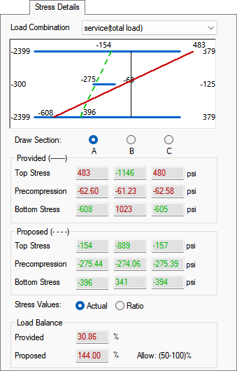
Below the Force Diagram the program reports the top and bottom stresses and precompression for each design section. Use the Stress Values radio buttons to choose to report either the Actual value of stress or the stress Ratio within the Provided and Proposed sections of Stress Details tab. Finally the user can see the provided and proposed load balancing percentages. The values in this window will be colored green if they are within the allowable limits and red if they exceed the allowable limits. The allowable limits for balanced loading are shown to the right of the Load Balance>Proposed status and can be modified in the Settings tab of the PT Strip Optimizer dialog window.
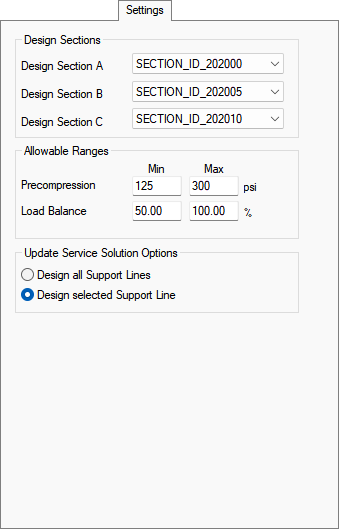
This section describes in detail the options of the Support Line Span Optimizer - Settings tab. For information on the general use of the Support Line Span Optimizer please refer to the beginning of the Support Line Span Optimizer topic.
The Settings tab allows the user to choose the design sections along the support line to use for optimization, set the Min and Max Precompression force and Load Balance percentage limits, and choose to design all support lines or the selected support line when using the Update Service Solution button of the PT Strip Optimizer. Once the user has selected the design sections and input the Allowable Ranges the solution shown on the Force and Stress Details tabs will be updated to reflect the changes.
This section describes in detail the use of the Update Service button in the Support Line Span Optimizer. For information on the general use of the Support Line Span Optimizer please refer to the beginning of the Support Line Span Optimizer topic.
After using the Apply to Model dialog to modify the tendon force for the tendons along the strip, the program will mark tendons that have been modified by the optimizer in a light orange color as shown in the following image.
Click on image to enlarge it
Any support line span that includes a tendon previously modified by the Support Line Span Optimizer can not be optimized until the solution has been updated. The user can either exit the tendon optimizer and run through the normal Analysis and Design workflow, or the user can use the Update Service Solution button in the Support Line Span Optimizer to update the solution. The advantage to using the Update Service Solution button is that it is a truncated analysis and design algorithm that only replaces the tendon block of the solution. This allows for a much faster run time than a full analysis and design would need. The Update Service Solution should only be used when iteratively designing tendons within the model.
To update the solution within the Support Line Span Optimizer:
After applying the tendon optimizer force changes to the tendons along the span, the user is returned to the Force tab of the PT Strip Optimizer window. The Force tab will be updated with the proposed solution and the tendons that have been modified by the solution will turn an orange color. To alert the user that the FEM solution is no longer in sync with the model, the word Pending is written in red text at the bottom of the PT Strip Optimizer window.
Click on image to enlarge it
The user can then click the Update Service Solution button in the PT Strip Optimizer dialog. This will open a load combination window where the user can select the service combinations they want to update the solution for.
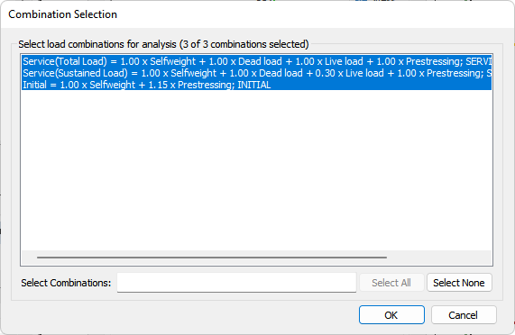
Click on image to enlarge it
Select the combinations you want to update.
Click the OK button to update the solution.
Once the analysis and design is completed the program will prompt you that the design is completed.
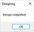
Click OK. The program will move you back to the Force tab of the PT Strip Optimizer dialog window showing the updated solution where you can optimize the same span again or choose another span to optimize.