
"Smart Tendons” are tendons that automatically insert points when they pass over a group of banded tendons or support lines, and/or cut themselves against the slab edges, openings, or user-defined regions. Creating individual tendons is as easy as drawing a construction line across the slab, partially within the slab, or completely in the slab. If the construction line starts or ends outside the slab, the tendon is snapped to the edge of the slab. Access the Smart Tendon Editor from the Tendon ribbon Modify panel Smart Tools icon.
Clicking on the Smart Tools icon will open the Smart Tendon Editor dialog window.
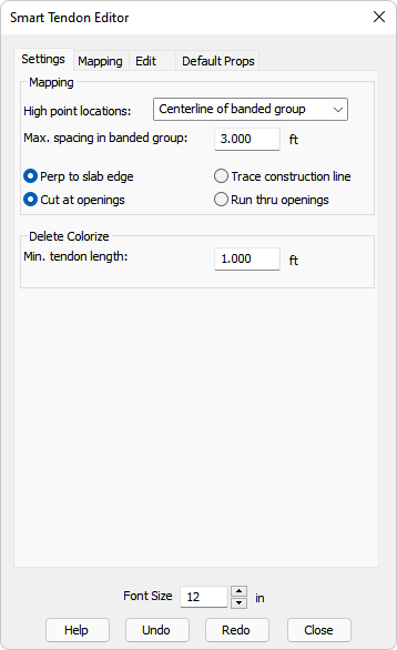
The Smart Tendon Editor contains four tabs; Settings, Mapping, Edit and Default Props (Default Properties). Each of these are described in the following sections.
The Settings tab allows you to define placement options for tendons and their control points using the tools in the Mapping tab. These options are used for creating individual tendons and mapped tendons. They control how tendons are created from the initial construction line relative to other objects in the model (slabs, openings, banded tendons, support lines). The Settings tab also allows you to specify the minimum length of tendons that the program checks against when in 'Mapping', 'Smart Tendon', 'Delete' mode.
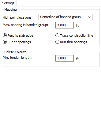
The tables in the following sections provide descriptions of the Settings tab sections and their options. The information is divided into two table; Mapping Options and Delete Colorize Option.
| Option | Description | ||||||||
|---|---|---|---|---|---|---|---|---|---|
|
High point locations |
This option determines where high points are added for the smart tendons, relative to crossing a group of banded tendons or a support line. Available options are:
|
||||||||
|
Max. spacing in banded group |
This option is used to determine which tendons are part of a banded group. It considers banded tendons closer than the given distance to be part of the same band. Banded tendons father from other banded tendons are considered a different group. |
||||||||
|
Perp to slab edge |
The new tendon is placed perpendicular to the slab edge it crosses first, regardless of its orientation relative to other slab edges it crosses. |
||||||||
|
Trace construction line |
The tendon is drawn along the construction line exactly as entered by you. |
||||||||
|
Cut at openings |
If the construction line crosses an opening in this mode, two new tendons are created and snapped to the outside edges of the opening. |
||||||||
|
Run thru openings |
If the construction line crosses an opening in this mode, the new tendon ignores the opening and is created as if the opening doesn't exist. |
| Option | Description |
|---|---|
|
Min. tendon length |
This option indicates that the tendon shorter than the length specified here, will be highlighted when you go to 'Mapping', 'Delete' mode. This gives you an overview of which tendons do not meet minimum length; you can delete them or modify them. |
The Mapping tab allows you to edit groups of tendons. You can create, delete, display information, distribute, modify points as a group and modify groups of tendons relative to other objects, like openings and slab edges.
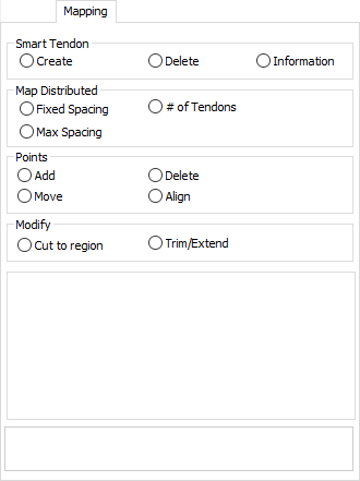
The tables in the following sections provide descriptions of the Mapping tab sections and their options. The information is divided into four groups; Smart Tendon Options, Map Distributed Options, Points Options and Modify Options.
The Smart Tool options in this section are used to view, create and delete smart tendons.
| Option | Description |
|---|---|
|
Create |
Choose this option if you want to easily create individual tendons by drawing a construction line across the slab, partially within the slab, or completely in the slab.
Click on image to enlarge The information on the Settings tab controls how tendons are created from the construction line; perpendicular to the slab edge or not, high points at the center of a group of banded tendons or on the edges of the banded group, or where the construction line crosses a support line. Tendon span shapes and other tendon properties are defined on the Default Props tab. |
| Delete (Tendons) |
Choose this option if you want to delete existing tendons. Select tendons to delete by drawing a construction line crossing the tendons to be deleted.
Click on image to enlarge |
| Information |
Choose this option if you want to display the average values along the selection line; Spacing, precompression (POA), number of tendons and number of stands. Values are displayed in the Show Mapping Information section of this tab after selection line has been drawn on screen across a group of tendons.
Click on image to enlarge |
The Smart Tool options in this section use the same 'Smart' logic as the Create tool, allowing you to add tendons at a given spacing.
To use these tools, select a mapping option and draw a selection line across two or more tendons. The outside two tendons will be used as boundaries for placing new tendons. The tendons in between the boundary tendons will be deleted and replaced with the new tendons. By default, the new tendons will extend across the region bound by the two boundary tendons and cover the entire slab in the direction parallel to the boundary tendons. Though, you can also define a region to limit the 'length' extent of the tendons. To enter this mode, select the Use mapping region checkbox.
The Smart Tool options in this section are used to indicate the number of smart tendons and/or their spacing.
| Option | Description |
|---|---|
| Fixed Spacing |
Choose this option when you want to add tendons at a given (fixed) spacing. Draw selection line across two or more tendons where:
Click on image to enlarge Based on the designed fixed spacing, the number of tendons is calculated and added to the space, starting with the first tendon and moving in the direction of the second tendon. The spacing between last added tendon and second boundary tendon might be less than user-defined fixed spacing. |
|
Max Spacing |
Choose this option when you want to add tendons at a uniform spacing that does not exceed maximum spacing defined by you. Draw selection line across two or more tendons where:
The program calculates the new uniform spacing to fill the space with tendons at the new calculated spacing without exceeding the max spacing input.
Click on image to enlarge |
|
# of Tendons |
Choose this option when you want to add a certain number of tendons. Draw selection line across two or more tendons where:
This number of tendons is used to calculate the new spacing to fill the space with the number of tendons input by you.
Click on image to enlarge |
|
Use Mapping Region |
Check this checkbox if you want to limit the extent of the mapping region. By default when this option is turned off (unchecked), the program attempts to cover the whole slab, when generating tendons at a spacing between boundary tendons. When limiting the extent of the mapping region, after you select the boundary tendons, you are prompted to draw a region. Right-click and choose Close/End/Accept to complete the region. The boundary tendons and region define the length/extent/direction of the new tendons. The boundary tendons govern the mapping extent, while the Mapping Region limits the length of added tendons. If the region is outside the slab, the tendons will be stopped within the slab edge. Note: This checkbox is applicable to all three Map Distributed Smart Tools.
This example shows where the Use mapping region checkbox is located for all three Smart Tools (Fixed Spacing, Max Spacing and # of Tendons).
|
The Smart Tool options in this section are used to work with tendon points.
| Option | Description |
|---|---|
|
Add |
Choose this option if you want to add high points or swerve points to tendons along a construction line across a group of tendons where:
When this option is chosen, you also need to choose the type of points to add, from the Add Points option.
Click on image to enlarge Once you've chosen the Point Type, you can draw a construction line across a group of tendons. If High Points is selected, new high points are added, that effectively split a span into two spans. If Swerve Pts is selected the new swerve points are added at the location where the construction line intersects the tendon. |
|
Delete |
Choose this option if you want to remove high points across a group of tendons which consolidate two spans into one span, or remove swerve points along spline and fillet tendons. When this option is chosen, you also need to choose the type of points to delete, from the Delete Points option.
Click on image to enlarge Draw a construction line across one tendon or a group of tendons, closer to the high points or swerve points to be deleted than other points on the tendon, that you want to delete. Those points will be deleted. NOTE: you cannot delete auto-swerve points. They are now shown in blue while user defined swerve points are shown in green. |
|
Move |
Choose this option if you want to move (translate) a group of high points or swerve points across a groups of tendons, where:
Click on image to enlarge Draw a construction line across one tendon or a group of tendons, closer to the high points or swerve points to be displaced than other points on the tendon, that you want to move. After the points are selected as you move the mouse, you'll see the points floating on the screen. Place them where you want them moved, then click the left mouse button. |
|
Align |
Choose this option if you want to select a group of high points or swerve points across multiple tendons and get them to line up along a straight construction line.
Click on image to enlarge Draw a construction line across one tendon or a group of tendons, closer to the high points or swerve points to be aligned than other points on the tendon, that you want to realign. Draw a second construction line that crosses the same tendon(s), the selected points then line up along the second construction line. |
The Smart Tool options in this section are used to modify smart tendons.
| Option | Description |
|---|---|
|
Cut to region |
Choose this option if you want to cut tendons to the outside of a region you define, where:
Click on image to enlarge The cut to region tool prompts you to draw a region. Right-click and select Close/End/Accept to complete the region and cut the tendons where they cross the region. |
|
Trim/Extend |
Choose this option if you want to move the endpoint of the tendon to hit the nearest slab edge within the trim tolerance, where:
When using this option, you'll need to define how much Trim Tolerance to use.
Click on image to enlarge Trim/Extend only works on the end span. If the end span is completely outside the slab, nothing will happen when applying Trim/Extend.
|
The Edit tab allows you to visually modify tendon properties for groups of selected tendons or spans or a single tendon or span at a time.
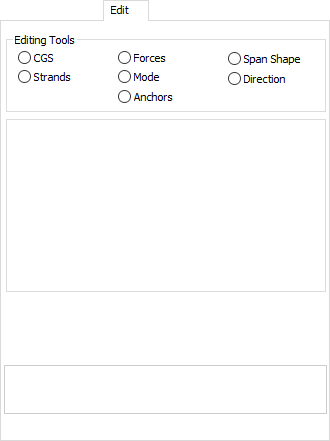
The table in the following section provides description of the various Smart Tools available on the Edit tab.
| Option | Description |
|---|---|
|
CGS |
Choose this option if you want to change the CGS for high or low points.
Click on image to enlarge Enter a new CGS, then draw a selection line across tendons close to the points you want to modify. The CGS is updated for the selected points. |
|
Forces |
Choose this option if you want to change the effective force of a group of tendons.
Click on image to enlarge Enter the new effective force, then draw a selection line across a group of tendons. The effective force is updated. |
|
Span Shape |
Choose this option if you want to change the shape of a tendon span along with the geometric ratios for that shape.
Click on image to enlarge Select the new shape, enter the new ratios for inflection point location where applicable, and then draw a selection line across a group of tendon spans. The span geometry is updated. |
|
Strands |
Choose this option if you want to change the number of stands for a tendon. The number of strands can be a decimal number.
Click on image to enlarge Enter the new number of stands, then draw a selection line across a group of tendons. The number of strands is updated. |
|
Mode |
Choose this option if you want to change the shape of the tendon in the X, Y plane to straight, spline or fillet.
Click on image to enlarge Select the mode you want to set, then draw a selection line across a group of tendons. The mode is updated. |
|
Direction |
Choose this option if you want to change whether the tendon is Banded, Distributed or Undefined.
Click on image to enlarge Select the type you want to set, then draw a selection line across a group of tendons. The type is updated. |
|
Anchors |
Choose this option if you want to change the angle where the end of a tendon meets a slab or opening edge, and how far from the end the effect is to be applied. Note: This option only works on tendons that are spline or fillet modes.
Click on image to enlarge Select the angle at which the tendon will meet the slab or opening edge, choose whether to use a percent of the end span length or a given length, to apply the length of the tendon that should follow the angle until it can deviate from this angle with the slab. Next, draw a selection line along the ends of a group of tendons, crossing the tendons, and if the tendons are spline or fillet mode. The end geometry is updated. Tendons are color-coded based on mode, so it's easy to know which tendons this tool will work with. |
The Default Props (properties) tab allows you to set default properties for new tendons that are being generated with the Create tool or any of the mapping tools. These are the tendon shape, force and strand properties that will be used when new tendons are created from the Smart Tendon Editor.
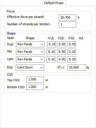
The tables in the following sections provide descriptions of the Default Props (properties) tab sections and their options. The information is divided into three groups; Force Options, Shape Options and CGS Options.
The Smart Tool options in this section are used to control the effective force and number of strands for each tendon created using the Mapping tools of the software.
| Option | Description |
|---|---|
|
Effective force per strand |
Allows you to set the effective force per strand of the tendons created by the Smart Mapping Tools. |
|
Number of strands per tendon |
Allows you to set the number of strands for each tendon created by the Smart Mapping Tools. |
The Smart Tool options in this section are used to define the properties for the default span shapes used along a tendon created using the Smart Tools.
| Option | Description |
|---|---|
|
Shape |
Allows you to enter the tendon profile shape used for the First, Mid, Last, and Cantilever Spans. |
|
X1/L |
Allows you to set the percentage of span for the first inflection point. Cannot be larger than X2/L. Can also be used to set the inflection point for the cantilever harped and cantilever partial shapes. |
|
X2/L |
Allows you to set the percentage of span for the low point of the tendon. Cannot be smaller than X1/L or X2/L. |
|
X3/L |
Allows you to set the percentage of span for the last inflection point. Cannot be larger than X2/L. |
|
A/L |
Allows you to set the percentage of the span to run straight at the low point of a harped tendon profile. Only available when Span is set to Harped. |
The Smart Tool options in this section are used to define the distance to the center of gravity of tendon from the top/bottom of the slab/beam.
| Option | Description |
|---|---|
|
Top CGS |
Allows you to set the default distance to CGS from top of slab/beam for the high points along tendons created using the Smart Tools. |
|
Bottom CGS |
Allows you to set the default distance to CGS from soffit of slab/beam for the low points along tendons created using the Smart Tools. |


