After wall design sections have been processed and updated for either design or code check, Graphical Results are available for review. A Wall Design Summary report can also be exported in a variety of formats. Each result option is described below.
Graphical results for walls can be viewed through the Results View Panel. Wall Design results can be found on the Analysis tab. The Display tab gives users options for modifying the display of the graphical results while the Colorize tab enables the user to colorize walls based on different properties.
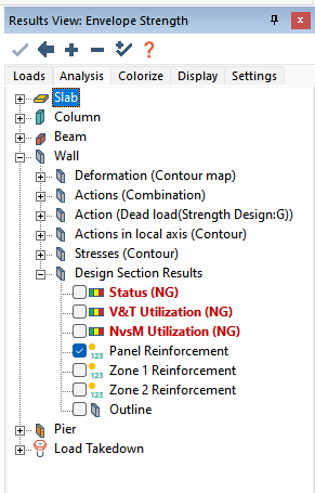
The Analysis tab of the Results View panel includes a Design Section Results branch under the Walls branch for viewing of wall design graphical results. Each option is defined below. Note that unless the wall design section is designed or code checked, the first three options will be reported as NA.

Available options to view graphically are:
Status – Value can be NA, acceptable, warning, borderline, or unacceptable. NA indicates that the design section has not yet been designed. If either utilization check fails to meet the specified utilization setting, unacceptable is reported in the form of a red design section. Green represents acceptable. When code checked, if the section fails a specific detailing/spacing requirement the warning value will be reported with a magenta color. Any section indicated with yellow means that the section is borderline. This occurs when the section is within 5% of the maximum utilization factor set by the user.
Click on image to enlarge.
V&T Utilization – Displays a gradient for utilization values of the sections with results for shear and torsion.
Click on image to enlarge.
NvsM Utilization – Displays a gradient for utilization values of the sections with results for axial and flexure.
Click on image to enlarge.
Panel Reinforcement – Displays panel reinforcement.
Click on image to enlarge.
Zone 1 Reinforcement – Displays Zone 1 reinforcement.
Click on image to enlarge.
Zone 2 Reinforcement – Displays Zone 2 reinforcement.
Click on image to enlarge.
Outline – Shows outline of the design sections that have been generated.
Click on image to enlarge.
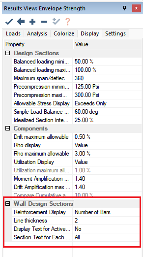
The Result Display tab in the Results View Panel includes a Wall Design Sections block that contains additional options allowing the user to control how the information is presented graphically.

Available options are:
Reinforcement Display – This value can either be set to Number of Bars, area, rho, or all. The application of this value is used for the display of the panel and/or zone reinforcement setting. The value only applies to the walls in view and the location set to be viewed (zone or panel). The image below shows the result for one wall with all selected.
Click on image to enlarge.
Line Thickness – Sets the line thickness for the design section outline.
Display Text for Active Level – The value for this option can be Yes or No. If No is selected, the program will show reinforcement for all walls in view and for the selected zones or panel. If Yes, is selected the program will display only the reinforcement information for the walls that reference the current active plane for the top of wall. The reinforcement will be shown for all walls in the model that are active in view and referenced from the current plane and for the panel or zones selected in Result Display Settings tab of the Results View Panel. This selection is useful when needing to view reinforcement for one plane only in a global top view. For example, the image below shows the plan view of Level 3 with panel reinforcement shown by area of steel.
Click on image to enlarge.
Section Text for Each Wall – This option allows the user to filter which design section for walls in view are shown. The values that can be set are all, top, or bottom. If all is used, top and bottom sections for walls displaying reinforcement will be shown. If top is selected, only the top design sections of walls will be displayed. If bottom is selected only the bottom design sections of walls will be displayed. The image below shows an example of Level 3 walls with Bottom selected for the Section Text for Each Wall option.
Click on image to enlarge.
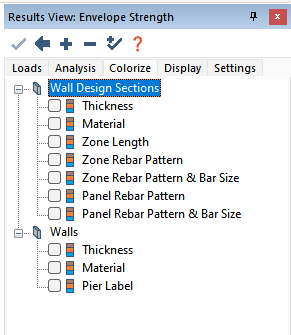
The Colorize tab in the Results View Panel includes two sections containing predefined selectable properties that can be graphically colorized for quick and efficient comparisons. These sections include Wall Design Sections and Walls.

Available options are:
Wall Design Sections
Thickness – The program will identify each wall design section with the same thickness as a unique color.
Click on image to enlarge.
Material – The program will identify each wall design section with the same material concrete material assignment as a unique color.
Click on image to enlarge.
Zone Length – The program will identify all wall design sections with same zone lengths at Zone 1 and Zone 2 ends and will assign a unique color to the design section. Zone assignment must be identical to be assigned to the same color group. For example, a wall with Zone 1 and Zone 2 having lengths of 30” at both ends would NOT be in the same group as a wall assigned with only Zone 1 having a length of 30” at and nothing assigned for Zone 2.
Click on image to enlarge.
Zone Rebar Pattern – The program will identify all wall design sections that have identical zone reinforcement patterns. This includes identical number of curtains, number of bars, and spacing. Similar design sections must have similar number of zones assigned to the section. For example, a section with only 1 zone defined cannot be grouped with a section having 2 zones defined.
Click on image to enlarge.
Zone Rebar Pattern & Bar Size – The program will identify all wall design sections that have identical zone reinforcement patterns and bars size. This includes identical number of curtains, number of bars, bar size, and spacing. Similar design sections must have similar number of zones assigned to the section. For example, a section with only 1 zone defined cannot be grouped with a section having 2 zones defined.
Click on image to enlarge.
Panel Rebar Pattern – The program will identify all wall design sections that have identical panel reinforcement patterns. This includes identical number of curtains and spacing for vertical and horizontal reinforcement.
Click on image to enlarge.
Panel Rebar Pattern & Bar Size – The program will identify all wall design sections that have identical panel reinforcement patterns and bars size. This includes identical number of curtains, bar size and spacing for vertical and horizontal reinforcement.
Click on image to enlarge.
Walls
Thickness - The program colorizes walls of similar thickness.
Click on image to enlarge.
Material - The program colorizes walls of similar material assignment for the wall concrete.
Click on image to enlarge.
Pier Label – The program colorizes walls with the same Pier Label/Assignment.
Click on image to enlarge.
The Wall Design Summary Report exports input and result data for the wall design sections in HTML, XLS, or PDF format. The below instructions assume a Code Check or Design of walls has been completed. The PDF format also contains an additional Wall Intersection report.
Go to the Wall Design ribbon and click on the Wall Design Manager icon.
icon.
Select the Design Section(s) within the Wall Design Section List that you want to create the report for.
Alternatively, you can right click on the design section in the model space and choose Wall Design>View Design Summary.
Click on image to enlarge.
An HTML report will be created and opened within your default web browser. An example of the Wall Design Summary Report created for the designed or code checked section is shown below.
Click on image to enlarge.
Similar wall design section result data can be combined into multi-page PDF report for all sections that have been code checked and/or designed.
Select the walls whose design sections you want to create the report for. If no wall is select the report will be created for all design sections visible on screen.
Go to the Wall Design ribbon click on the Wall Design Summary icon. Alternatively you can go to the Wall Design or Reports ribbon and select Wall Reporting>PDF Reports>Wall Design Summary.
A PDF report will be created containing the Wall Design Summary report, the section from the graphical wall section window for each section, and the P-M Diagram for the sections. Please click here to open an example PDF.
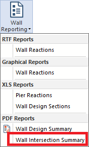
The PDF format is also applied to a single page report containing Wall Intersection layouts. This is a one-page report produced only for the active level.
Using the Level Manager make the plane, whose wall intersection report you want to create, the active plane.
Go to the Wall Design ribbon and select Wall Reporting>PDF Reports>Wall Intersection Summary.

A PDF report will be created containing the Wall Intersection Summary report for the active level. Please click here to open an example PDF.
The same report data found in the PDF Wall Design Summary Report can be generated in XLS format for all wall design sections.
Go to the Wall Design or Reports ribbon and select Wall Reporting>XLS Reports>Wall Design Sections.
This will launch Microsoft Excel® and open the .XLS report. An example of the XLS report can be downloaded here.