You may calculate and report inter-story drift based on calculated displacements in the X-direction.
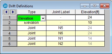
The Drift Definitions spreadsheet defines where the drift calculations will be performed. Drift calculations may be performed at specific elevations . However, these elevations must be manually entered by the user in the Drift Definitions spreadsheet. These elevations are defined with respect to the vertical axis of the model.
In addition, the user may specify individual to be used in drift calculation. definitions are included for a number of reasons. They allow models defined in older versions of the program (which only used defined "story joints") to produce identical drift results in the current version. They also allow users to get drift reporting at specific points of interest even if these points don't line up well from floor to floor or don't behave the same as other at that elevation. See Drift Modeling Tips for more information.
Note
To Define an Elevation for Drift Calculation
Note
To Define a for Drift Calculation
Note
For additional advice on this topic, please see the RISA Tips & Tricks webpage at risa.com/post/support. Type in Search keywords: Story Drift.
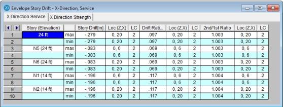
Once the solution is performed you may view the drift results in the Story Drift spreadsheet. Access the Story Drift spreadsheet by selecting it from the Results menu. This report lists the drift for all defined Diaphragms, Elevations and that exist in the Drift Definitions spreadsheet. The results are reported in the order in which they appear in the Drift Definitions spreadsheet.
To calculate inter-story drift for a particular direction, the displacement at the lower level is subtracted from the current story displacement. For example, to calculate X direction drift for story 2, the X displacement for the representing story 1 is subtracted from the X displacement for the representing story 2.
For Elevation definitions, the drift calculations are only done at locations where columns or walls have at the current level and at the level below.
For Definitions, the calculations are done for the current defined drift compared to the nearest defined drift at a the level below. definitions never look at the in a Elevation definition. These are user-defined drift which act completely independent of the more automated Diaphragm and Elevation drift results and offer flexibility for cases where the Elevation options don't give the output needed.
For story height, the vertical axis is used to determine the distance. For example, the story Y coordinate values are used to calculate heights for X direction drift.
The base elevation of the structure is assumed to be zero. If the 0 ft elevation should NOT be used as the base of the structure for drift calculations, then the user should enter in an Elevation entry in the Drift Definitions spreadsheet to define the elevation of the base of the structure. This applies whether the base is a positive or negative value. If the value is positive, then there will be a reported drift (probably zero) at the base elevation that can be ignored by the user.
Service level and strength level drifts are reported on different tabs of Drift Results Spreadsheet. This is because seismic drift checks are usually checked purely for the strength level Load Combinations while wind drift is usually checked against service level Load Combinations.
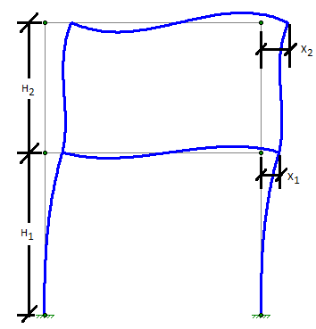
The Drift at a given level is equal to the deflection at that level minus the deflection at the level below. For the image below:
1st Level Drift = X1
2nd Level Drift = X2 - X1
The Drift Ratio (%) is equal to the drift at that level divided by the height from that level to the level below. For the image below:
1st Level drift ratio % = (X1 / H1 ) *100%
2nd Level drift ratio % =((X2 - X1) / H2 ) *100%
Seismic drift are reported for all codes for load combinations containing earthquake loads, but the program will report failures in red text for the ASCE 2005, 2010, and 2016 codes based on the following table of allowable seismic drift versus Risk Category / Occupancy Category:
| Drift Category | I or II | III | IV |
|---|---|---|---|
|
High Drift Design |
2.5% |
2% | 1.5% |
|
Masonry Cantilever |
1% |
1% | 1% |
|
Other Masonry |
0.7% |
0.7& | 0.7% |
|
Other |
2% |
1.5% | 1% |
When the ASCE and IBC codes are used, the Story Drift for the strength level combinations will account for the inelastic deflection (i.e. the Cd factor) by amplifying the deflections at each level by Cd/ I per Section 12.8.6 of ASCE-7. Where Cd is the Deflection Amplification factor intended to convert the elastic deflection levels given in the analysis to the inelastic levels used for seismic drift checks. Similarly, I is the importance factor (based on Risk / Occupancy Category) which was presumably used to amplify the seismic forces applied to the structure.
For codes other than the US codes the drift results are not modified for Cd, I or rho, and are never reported in red text to indicate a failure.
Note
The program will report the ratio of 2nd order deflection to 1st order deflection for the used in the drift calculation. This is useful when determining whether it is required by the AISC code to use the Direct Analysis Method. In general, if the ratio is greater than 1.5 (or 1.7 if stiffness adjustment has been turned on) then you MUST use the Direct Analysis Method on your structure.
To facilitate this check, RISA will color the check in red whenever the ratio exceeds the 1.5 limit (or 1.7 when stiffness adjustment is used). This is done regardless of what has been chosen for the HR steel code. While the 1.5 or 1.7 may not be a code trigger in other HR steel codes, it remains because it can be an indicator of when 2nd order effects become troublesome.
There is an internal tolerance of 0.0005 inches, below which the deflection will not be reported in drift results. This is because while the drift is essentially zero, testing showed cases where minor increases in these small values could result in high 2nd order / 1st order deflection ratios. Which were falsely indicating 2nd order effects as reaching high or troublesome levels.
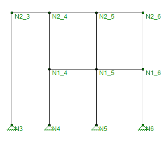
When using elevations, the drift is reported for aligned connected by columns or walls. This doesn't help for inclined columns because those will very specifically NOT align from level to level. If drift reported is required for these , then they should be defined using the option instead. When defined this way, the drift from level to level will be reported based on the nearest at the level below.
In the image below, N2_3 should have its drift calculated based on a story height that is twice what the other at that level would be based on. In that case, the user should use Elevationdefinitions for the majority of the , but use definitions for N2_3.
There are times when drift results will be reported as "NC" (which stands for Not Calculate). This can occur for a number of reasons: