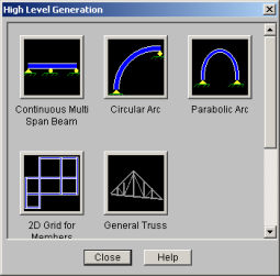
You may automatically generate regular structures or portions of structures to start a new model or add to an existing model.
Access the Generation types by clicking
![]() on the RISA toolbar. You will see the
following options, which require you to specify basic parameters to generate
structures with beam elements, plates, or a combination of both.
on the RISA toolbar. You will see the
following options, which require you to specify basic parameters to generate
structures with beam elements, plates, or a combination of both.
Note
The Continuous Beam generation will produce a complete model of various types of beams. You can simultaneously generate the beam geometry, section properties, boundary conditions, uniform distributed loads, and unbraced lengths for code checking.
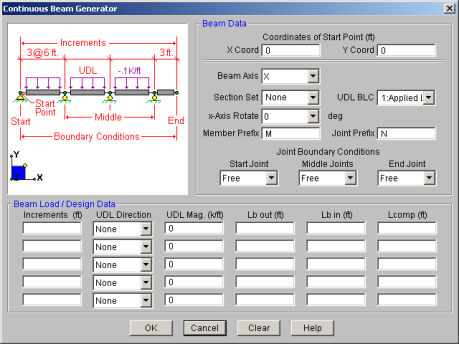
Specify the start point for the beam generation. This defines the first point for beam and is also the “Start Joint” for any boundary conditions.
Choose which axis you want to be the longitudinal axis of the beam. ( I.e., the beam will run parallel to this axis ).
To generate members for the beam, you must select a valid section set. This section set will be used for all parts of the beam. If you don’t select a section set, you will just get a sequence of joints.
If you are generating loads, select a Basic Load Case for any distributed loads. All the loads will put into this basic load case.
For any generated members, you may assign a “x-axis rotate angle”, and member label prefix. The “x-axis rotate” may be used to rotate the local axes to a desired orientation.
You may optionally enter a Joint label prefix which will be used for all the joints generated as part of the beam. This is useful if you want a way to track individual parts of your model by looking at joint prefixes.
You can also generate boundary conditions for the joints along the continuous beam. You can specify different boundary conditions for the Start Joint, all the middle joints, and the End Joint. You choices for the boundary conditions are Free, Roller, Pinned, and Fixed. These are just like the regular boundary conditions that you would assign elsewhere in the program. The “Free” option is useful for the first or last joint if you want a cantilever overhang. The “Roller” option will only restrain the vertical translation. The “Pinned” option will restrain all the translations. The “Fixed” option restrains all the translations and rotations. See Boundary Conditions for more information.
Special symbols may be used to define multiple equal increments:
The “@” entry may be used to specify multiple, equally spaced, grid increments. For example, if you wanted 7 increments at 10 units each, you would type “7@10”.
The “/” entry subdivides a larger increment into smaller equal increments. For example, the entry “12/4" would create 4 increments of 3 units each.
Use commas (“,”) to enter multiple increments in a single edit field. For example, if you wanted to define increments of 3, 4, 7 and 2 units, you could enter each increment in a separate field, or you could enter “3,4,7,2" in a single field to get the same result.
With each increment, you can also generate distributed loads by selecting a valid distributed load category and direction, and assigning a load magnitude.
Lastly, you can also generate unbraced lengths for your increments. These are used by the code checking to calculate axial and flexural stresses or strengths depending on what design code you are using. See Hot Rolled Steel Design and Wood / Timber Design for information on member design.
The circular arc generation enables you to generate a full circle or partial arc comprised of beam elements.
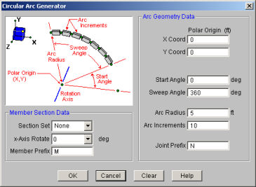
The polar origin is the center point of the arc. You may generate an arc the full 360 degrees around the axis of rotation or generate a partial arc by specifying the start and sweep angles.
The arc radius is the length from the polar origin to the arc. The arc increment determines how many piecewise straight segments are used to model the arc.
To generate members for the arc, you
must select a valid section set. This section set will be used for
all parts of the arc. If you don’t select a section set, you will
generate an arc of joints without members. The “x-axis
rotate” may be used to rotate
the local axes to a desired orientation, however you may find that a
For additional advice on this topic, and how to use the Circular Arc to model a Dome structure, please see the RISA Tips & Tricks website: www.risa.com/post/support. Type in Search keywords: 3D Dome.
The Parabolic Arc generation is
used to make arcs that are parabolic. The arc model will be comprised
of
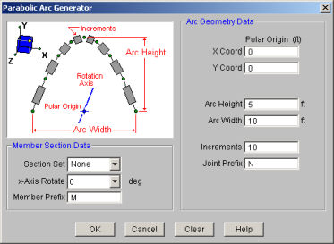
Specify the polar origin about which the arc will be generated.
You must enter the arc height and the arc width.
Enter the number of arc increments to be used to model the arc. The more increments used, the more closely the final geometry will follow the desired parabola. The minimum increments are two, which will give you a triangular shape.
You may optionally enter a
To generate members for the arc, you
must select a valid section set. This section set will be used for
all parts of the arc. If you don’t select a section set, you will
generate an arc of
This generation enables you to generate
2D (or even 1D (line) grids) of
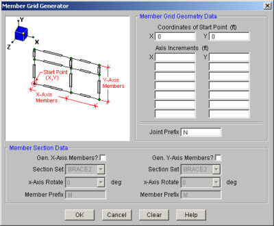
Define the X and Y coordinates of the
Special symbols may be used to define multiple equal increments:
The “@” entry may be used to specify multiple, equally spaced, grid increments. For example, if you wanted 7 increments at 10 units each, you would type “7@10”.
The “/” entry subdivides a larger increment into smaller equal increments. For example, the entry “12/4" would create 4 increments of 3 units each.
Use commas (“,”) to enter multiple increments in a single edit field. For example, if you wanted to define increments of 3, 4, 7 and 2 units, you could enter each increment in a separate field, or you could enter “3,4,7,2" in a single field to get the same result.
You may create members in the global directions between the grid points. You may use different section sets in the three global directions. For example if the Y-axis is the vertical axis you can specify a column shape for the Y-axis members and different or similar beam shapes for the X-axis members.
You may have unique labels assigned to the generated members, by entering a start label, and you may also use different labels for the three member directions.
The general Truss Builder generation is
used to make various trusses and various forms of truss joists.
The truss will be comprised of
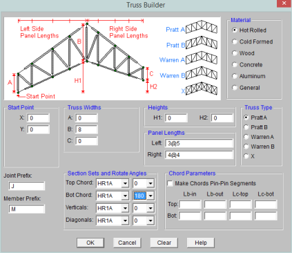
The start point for the truss generation defines the first point of the bottom chord.
You must enter the truss height and
the panel lengths to the left and right of truss "peak".
The "@" entry may be used to specify multiple, equally spaced panels. For example, if you wanted 7 panels at 10 units each, you would type "7@10" in the panel lengths as shown in the image below.
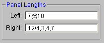
The "/" entry subdivides a larger panel length into smaller, equal increments. For example, the entry "12/4" would create 4 panels of 3 units each as shown in the image above.
Use commas (",") to enter multiple, varied panel lengths. For example, if you wanted to define panels of 3, 4, and 7 units, you could enter "3,4,7" in the increment field as shown in the image above.
The Truss Type selects what configuration the truss will use. The Truss Plane defines the plane of the truss.
You can vary the elevation of the bottom chord by setting the Heights (H1 and H2). You may adjust the elevation of the top chords by adjusting the truss Widths (A, B, C).
You may optionally enter a
You may optionally create members for the bottom chord, top chord, vertical strut, and diagonal brace. For each one of these members you must assign a valid independent section set, and “x-axis rotate angle”. Note that you must mark the checkbox for a member type before you can set any of the values to indicate that you want generation performed for that member type.
The “x-axis rotate” may be used to rotate the local axes to a desired orientation.
The Grid Plate generation is used to make 2D grids comprised of joints and optional plates.
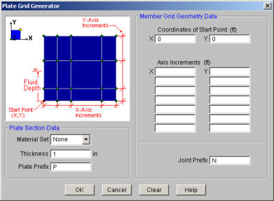
Simply define a starting point (enter the X and Y coordinates of that point) and then define the increments for grid spacing in both global directions. Negative increments are OK. Joints are created at all the grid intersection points.
Special symbols may be used to define multiple equal increments:
The “@” entry may be used to specify multiple, equally spaced, grid increments. For example, if you wanted 7 increments at 10 units each, you would type “7@10”.
The “/” entry subdivides a larger increment into smaller equal increments. For example, the entry “12/4" would create 4 increments of 3 units each.
Use commas (“,”) to enter multiple increments in a single edit field. For example, if you wanted to define increments of 3, 4, 7 and 2 units, you could enter each increment in a separate field, or you could enter “3,4,7,2" in a single field to get the same result.
You may also have plates created between the grid points and have unique labels assigned to the generated plates, by entering a start label.
A valid material set must be selected in order for plates to be generated. The default is “None”, so you will need to select a material from the list of currently defined material labels to generate your plates.
A hydrostatic load may also be generated along the grid of plates as you generate it. The hydrostatic load will be generated using a series of uniform surface loads on your plate elements. If the fluid depth is constant along the grid, you will just get uniform loads on your plates. If the fluid depth varies along the grid, you will get a series of uniform surface loads that increase in a “stair step” fashion , as you move down the fluid depth. The value of each uniform surface load is equal to the value of the actual hydrostatic load at the mid-point of the plate. The load direction will be perpendicular to the plates.
The fluid depth is measured in the positive vertical direction from the starting point for the plate grid.
The default fluid density is for water, but any density can be entered. The Fluid Load BLC provides a drop down list of all the Basic Load Cases. If you’ve defined in any descriptions for your BLC’s, these will be shown in the drop down list. The surface loads generated will be placed in the selected Basic Load Case.
The Circular Disk generation enables you to generate a circular disk comprised of plate elements.
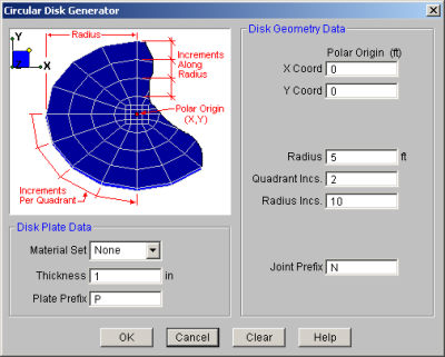
Specify the polar origin as the point about which the grid rotates. The grid is generated the full 360 degrees around the axis of rotation.
The radius is total length from the polar origin to the outer edge of the grid. The quadrant increment determines how many piecewise straight segments are used to model the sweep for each quadrant of the arc. Note this entry must be a multiple of 2 (2,4,6, etc.) due to modeling constraints at the center of the disk. The radius increment specifies how many “rings” to use to create the grid.
You must enter a material set and thickness to have plates defined. Only quadrilateral plates are generated. You may also specify labels assigned to the plates.
The circular radius
generation enables you to generate a full or partial circular grid
comprised of
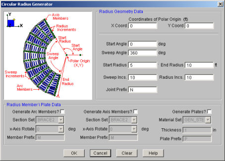
The polar origin is the center point of the disk. You may generate a grid the full 360 degrees around the axis of rotation or generate a partial grid by specifying the start and sweep angles.
The start radius is the radius of the “hole” in the center. This distance must be greater than zero and less than the end radius entry. The end radius is total length from the polar origin out to the edge of the grid. The number of increments along the radius tells RISA-2D how many “rings” to use to create the grid. The sweep increment determines how many piecewise straight segments are used to model the arc.
There are entries for a section set for both the arc members and the radius members so these two sets of members can be different sizes. To generate these members you must select a valid section set. If you don’t select a section set, you won't generate these members. You may also have unique labels assigned to the generated members by entering a start label.
Finally, you enter a material set and thickness to have plates defined. Only quadrilateral plates are generated. You may also have unique labels assigned to the generated plates by entering a start label.