Flexible Diaphragms
Flexible diaphragms distribute loads to elements which connect to them solely based on the tributary area of the element within the plane of the diaphragm.
Flexible Diaphragms in a RISA-3D Only Model
The diaphragm feature in RISA-3D cannot be used to create a flexible diaphragm. To consider a flexible diaphragm in RISA-3D there are a couple of options. The main option is to manually calculate how much force is going to each frame or shear wall in the lateral system and apply that load directly to those elements as a point or distributed load. Another option is to essentially use a semi-rigid path to use plates with an equivalent thickness and material properties as your diaphragm. You may choose a very small equivalent thickness which will still be semi-rigid, but much closer to flexible than rigid.
Flexible Diaphragms in a Combined RISAFloor/RISA-3D Model
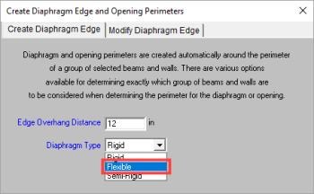
A flexible diaphragm can be defined in a combined RISAFloor/RISA-3D model. For wood diaphragms, the program actually designs the sheathing and nail spacing, incorporating the code specified design tables from the NDS/IBC. See the Diaphragms - Analysis & Results topic for more information on how the design works and how loads are attributed both for wind and seismic loads. The diaphragm can be defined as flexible when drawing the deck edge or from the Diaphragms spreadsheet.
Flexible diaphragms within RISAFloor/RISA-3D are used solely as load-attribution devices, and do not exist as elements within the stiffness matrix, unlike rigid or semi-rigid diaphragms. Flexible diaphragms have no stiffness, and are incapable of transferring load from one element within them to another. Thus, members that do not have lateral resistance out of plane are susceptible to stability issues. To increase stability in a model with a flexible diaphragm, it may be necessary to add small springs in the out-of-plane directions on the frames at the tops of the columns. This will stabilize the members while generally having a minimal effect on the analysis of the model.
Ceiling Diaphragm (Sloped Roofs)
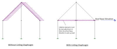
When a flexible diaphragm is applied to a sloped roof in RISAFloor, a setting exists to specify whether a ceiling diaphragm is present.
Click on image to enlarge it
The load attribution for the flexible diaphragm occurs only for Lateral Members from RISAFloor when a ceiling diaphragm is not specified. This is illustrated above where the lateral load follows the rafters. When a ceiling diaphragm is specified, it is necessary to draw in collector beams at the ceiling elevation so that the load can be carried directly the columns or walls at the base of the sloped members. With a ceiling diaphragm, the sloped members will not experience any lateral load directly. Note that the same total amount of lateral force will be applied regardless of this setting. This only controls whether the lateral load is applied to the sloped members, or in a horizontal flat plane.


