Drift
You may calculate and report inter-story drift based on calculated
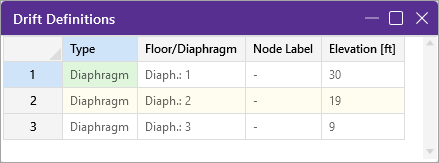
Drift Definitions Spreadsheet
The Drift Definitions spreadsheet defines where the drift calculations will be performed.
In addition, you can specify individual
- Elevations
- When Elevations are entered manually, there MUST be defined
- When
- The Drift Definitions spreadsheet is currently applicable to rigid diaphragms only.
Inactive Diaphragms
Drift is not reported for elevations that have been flagged as "Inactive" on the Diaphragms Spreadsheet. However, the inactive diaphragm is still considered for the drift calculation for the floor above, in the determination of story height.
No Wind / Drift Checkbox
When the No Wind / Drift box is checked on the Diaphragms Spreadsheet, then that diaphragm will be completely ignored for drift calculations. Drift will not be reported at that level. It will also not affect the story height calculation for the floor above or below.
Define Elevation for Drift Calculation
To Define an Elevation for Drift Calculation:
- Open the Drift Definitions spreadsheet from the ‘Explorer’ panel.
-
Add a new row to the spreadsheet:
-
Right-click in the spreadsheet to open an options menu.
-
Click on either Add New Row to End or Insert Row Above Selected, depending on where you want the new row to appear in the spreadsheet.
-
-
Click the Type column down-arrow in the new row.

Click on image to enlarge it
-
Click on Elevation in the list that appears.
This indicates the type of drift definition you are creating.
-
Click in the Elevation [ft] column of the new row and type the value for the elevation, as shown in the following image.

Click on image to enlarge it


Define Node for Drift Calculation
To Define a
- Open the Drift Definitions spreadsheet from the ‘Explorer’ panel.
-
Add a new row to the spreadsheet:
-
Right-click in the spreadsheet to open an options menu.
-
Click on either Add New Row to End or Insert Row Above Selected, depending on where you want the new row to appear in the spreadsheet.
-
-
Click the Type column down-arrow in the new row.

Click on image to enlarge it
-
Click on
This indicates the type of drift definition you are creating.
-
Click in the

Click on image to enlarge it


For additional advice on this topic, please see the RISA Tips & Tricks webpage at risa.com/post/support. Type in Search keywords: Story Drift.
Drift Results
Open the Story Drift Spreadsheet
Once the solution is performed you may view the drift results in the ‘Story Drift’ spreadsheet.
To open the Story Drift spreadsheet:
-
Ensure you have “Solved” the model so that the Results section appears in the Explorer panel.
-
Click on Story Drift in the Explorer panel under the Results section.
This opens the Envelope Story Drift results report/spreadsheet to the first tab.

Click on image to enlarge it
This report lists the drift for all defined Diaphragms, Elevations and
-
Click on the X Direction Service tab (if not already open) to view its results.
Service level and strength level drifts are reported on different tabs of the Envelope Story Drift results spreadsheet. This is because seismic drift checks are usually checked purely for the strength level Load Combinations, while wind drift is usually checked against service level Load Combinations.

How Drift is Calculated
-
Inter-Story Drift: To calculate inter-story drift for a particular direction, the displacement at the lower level is subtracted from the current story displacement.
For example, to calculate X direction drift for story 2, the X displacement for the
-
-
-
Story Height: For story height, the vertical axis is used to determine the distance.
For example when the Y-axis is specified as the vertical axis, the story
-
Structure Base Elevation: The base elevation of the structure is assumed to be zero. If the 0 ft elevation should NOT be used as the base of the structure for drift calculations, then you should enter in an Elevation entry in the Drift Definitions spreadsheet to define the elevation of the base of the structure. This applies whether the base is a positive or negative value. If the value is positive, then there will be a reported drift (probably zero) at the base elevation that you can ignore.
Story Drift and Drift Ratio %
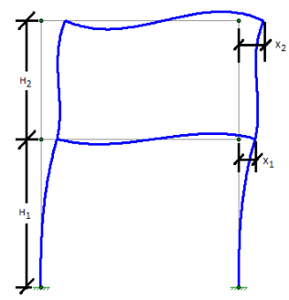
The Drift at a given level is equal to the deflection at that level minus the deflection at the level below. For the image below:
1st Level Drift = X1
2nd Level Drift = X2 - X1
The Drift Ratio (%) is equal to the drift at that level divided by the height from that level to the level below. For the image below:
1st Level drift ratio % = (X1 / H1 ) *100%
2nd Level drift ratio % =((X2 - X1) / H2 ) *100%
Seismic Drift Checks
Seismic drift are reported for all codes for load combinations containing earthquake loads, but the program reports failures in red text for the ASCE 2005, 2010, and 2016 codes, based on the following table of allowable seismic drift versus Risk Category / Occupancy Category.
| Drift Category | I or II | III | IV |
|---|---|---|---|
|
High Drift Design |
2.5% |
2% | 1.5% |
|
Masonry Cantilever |
1% |
1% | 1% |
|
Other Masonry |
0.7% |
0.7& | 0.7% |
|
Other |
2% |
1.5% | 1% |
When the ASCE and IBC codes are used, the Story Drift for the strength level combinations accounts for the inelastic deflection (i.e. the Cd factor) by amplifying the
For codes other than the US codes, the drift results are not modified for Cd, I or rho, and are never reported in red text to indicate a failure.
- These seismic checks are only performed for strength level load combinations.
- Stiffness reduction (per AISC Direct Analysis Method) does NOT change the drift code checks in RISA even though it may cause significant increase the reported drift.
- Load Combinations with Overstrength (Omega) seismic loading are not included in the drift reporting at all.
- To negate the effect of the redundancy factor (rho), the
2nd Order / 1st Order Deflection Ratio
The program reports the ratio of 2nd order deflection to 1st order deflection for the
To facilitate this check, RISA colors the check in red whenever the ratio exceeds the 1.5 limit (or 1.7 when stiffness adjustment is used). This is done regardless of what has been chosen for the HR steel code. While the 1.5 or 1.7 may not be a code trigger in other HR steel codes, it remains because it can be an indicator of when 2nd order effects become troublesome.
There is an internal tolerance of 0.0005 inches, below which the deflection is not reported in drift results. This is because while the drift is essentially zero, testing showed cases where minor increases in these small values could result in high 2nd order / 1st order deflection ratios. Which were falsely indicating 2nd order effects as reaching high or troublesome levels.
Drift Modeling Tips
Inclined Columns
When using
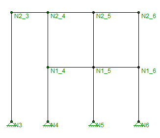
Multi-Story Columns
In the image below,
Troubleshooting NC results
There are times when drift results are reported as "NC" (which stands for Not Calculate). This can occur for a number of reasons:
- The Story Drift for that floor is below the 0.005" minimum tolerance for reporting.
- If a diaphragm is flagged as inactive then all results for that diaphragm will report NC.
- When there are no aligned drift
- The 2nd / 1st Ratio will report NC for any load combinations where a P-Delta analysis was not included in the solution.