Cylinder Generation
The Cylinder Plates / Members generation is used to make cylinders comprised of
Click on image to enlarge it
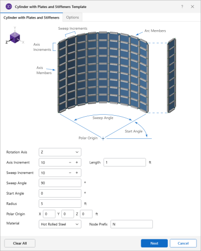
The following table provides descriptions for the options under both the Cylinder with Plates and Stiffeners and Options tabs in the Cylinder Template window.
Cylinder Plates / Members Template Options
|
Option |
Description |
|---|---|
|
Cylinder with Plates and Stiffeners - tab |
|
|
Rotation Axis |
The Rotation Axis defines the axis to which the direction of the cylinder is oriented. |
|
Axis Increment |
The Axis Increment defines the number of segments the cylinder is broken down into along the height of the cylinder. |
|
Sweep Increment |
The Sweep Increment defines the number of segments the cylinder is broken down into along the width of the cylinder. The number of Sweep Increment determines how many piecewise straight segments are used to model the arc of the cylinder. The number and length of increments along the axis of rotation is used to "extrude" the cylinder in the direction of the axis of rotation. |
|
Sweep Angle |
The Sweep Angle defines the ending angle of the cylinder arc. |
|
Start Angle |
The Start Angle defines the starting angle of the cylinder arc. |
|
Radius |
The Radius is the distance from the polar origin to the furthest point on the cylinder. |
|
Polar Origin |
The Polar Origin defines the reference point from which the arc height and width are measured and the rotation axis is defined. The Polar Origin is the point about which the arc rotates and a global axis is the axis of rotation. You can generate a cylinder the full 360 degrees around the axis of rotation or generate a partial cylinder by specifying the start and sweep angles. |
|
Material |
The Material option defines the material used to assign properties to the cylinder members. |
|
Node Prefix |
The Node Prefix Defines the prefix used in the node label for each new node generated. |
|
Options - tab |
|
|
Axis Members |
(checkbox) The Axis Member option allows you to toggle members being drawn in the Axis. |
|
Arc Members |
(checkbox) The Arc Member options allows you to toggle members being drawn in the arc. |
|
Section Set |
Section Set defines the section set assigned axis members or arch members. There are entries for a Section Set for both the arc members and the axis members, so these two sets of members can be different sizes. To generate these members you must select a valid section set. If you don't select a section set, you won't generate these members. Different labels may be assigned to the two member types. |
|
X-Axis Rotate |
The X-axis Rotate option defines the local x-axis rotation of the arc relative to the global X axis. It can be used to rotate the
local axis in to place. However, you may find that a |
|
Member Prefix |
The Member Prefix defines prefix to member labels for members created using the generator. |
|
Plates |
(checkbox) The Plates option allows you to draw plates between members generated using the Grid Generation. |
|
Material Set |
You must enter a Material Set for plates to be defined and the label prefix may be specified as well. |
|
Thickness |
You must enter Thickness for plates to be defined and the label prefix may be specified as well. |
|
Plate Prefix |
The Plate Prefix defines prefix to plate labels for plates created using the generator. |
|
Fluid Load |
(checkbox) The Fluid Load option allows you to automatically generate hydrostatic loads to the generated plates. |
|
Depth |
The Depth option defines the height of which the hydrostatic loads should be applied onto the structure. |
|
Density |
The Density option defines the density of the hydrostatic load that is applied to the structure. |
|
BLC |
The BLC option defines the Basic Load Case at which the hydrostatic loads are generated. |
