Drawing Grid
The Drawing Grid is a tool that lets you draw new
Drawing Grid Features
The Drawing Grid tools can be found on the Drawing Tools ribbon. These features allow you to define, save and reuse rectangular, radial and DXF underlay drawing grids. You can also set a specific grid as your default.

Click on image to enlarge it
To use the Drawing Grid features refer to the following table and sections.
Drawing Grid Features
|
Feature |
Description |
|---|---|
|
Drawing Grid section |
|
|
|
The ‘Display Grid’ icon lets you turn on (show) or off (hide) the drawing grid in the current model.
See Show / Hide the Drawing Grid for more information.
|
|
Type |
The ‘Type’ feature lets you choose |
|
Plane |
The ‘Plane’ feature lets you place the grid in any one of the three global planes. |
|
Color |
The ‘Color’ feature lets you choose what color you would like the drawing grid lines displayed in. |
|
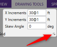
X Increments__ft |
The ‘X Increments’ feature lets you set the number of and width between the drawing grid lines. |
|
Y Increments__ft |
The ‘Y Increments’ feature lets you set the number of and height between the drawing grid lines. |
|
Skew Angle__deg |
The ‘Skew Angle’ lets you skew the drawing grid perpendicularly to the global axis plane. |
|
The icon located to the bottom right of the ‘Skew Angle’ feature lets you open the “Rectangular Grid Increments” window.
Click on image to enlarge it The “Rectangular Grid Increments” window lets you enter more X and Y incremental values. |
|
|
Drawing Grid Origin section |
|
|
X__ft |
The ‘X’ grid origin lets you set the increment, in feet, for the X direction. For more information see Rectangular Drawing Grid. |
|
Y__ft |
The ‘Y’ grid origin lets you set the increment, in feet, for the Y direction. See Rectangular Drawing Grid for more information. |
|
Z__ft |
The ‘Z’ grid origin lets you set the increment, in feet, for the Z direction. See Rectangular Drawing Grid for more information. |
|
|
The ‘Click to Locate’ icon lets you specify or relocate the origin of the drawing grid. See Relocating the Drawing Grid for more information. |
|
Save and Recall features section |
|
|
|
The ‘Save as Default’ feature lets you save any of the grid information as the default settings so that when you start a new model that information is already there. See Save a Drawing Grid Default for more information. |
|
|
The ‘Save Grid’ feature lets you save a drawing grid so you can recall it for later use. Saved drawing grids are model independent, i.e. when you save a grid, you can reuse it in any other model you are working with in the future. See Save a Drawing Grid for more information. |
|
|
The ‘Load Grid’ feature lets you recall a saved drawing grid. See Recall a Drawing Grid for more information. |

Show / Hide the Drawing Grid
The ribbon includes a feature that works like a toggle; allowing you to show or hide the drawing grid in the current model.
To show or hide the drawing grid:
-
Open to the Drawing Tools ribbon.

Click on image to enlarge it
-
Click on the Display Grid icon.
-
When the Display Grid slider is blue, it indicates that the drawing grid is turned ‘on’ (shown).
-
When the Display Grid slider is gray, the drawing grid turned ‘off’ (hidden).
-
Drawing Grid Type
Rectangular Drawing Grid
The rectangular drawing grid is defined by increments in two directions. The X, Y, Z Origins are where you want the grid increments to start. The X, Y, Z Increments are the distances between the grid points or lines in two global directions.

Click on image to enlarge it
You may use symbols such as "@", "/" and "," when entering the drawing grid increments.
-
The "@" entry may be used to specify multiple, equally spaced, grid increments.
For example, if you wanted 7 increments at 10 units each, you would type "7@10" in the increment field.
-
The "/" entry subdivides a larger increment into smaller equal increments.
For example, the entry "12/4" would create 4 increments of 3 units each.
-
Use commas (",") to enter multiple increments in the increment field.
For example, if you wanted to define increments of 3, 4, 7 and 2 units, you could enter "3,4,7,2" in the increment field.
Once the drawing grid is specified and displayed in the model view, it provides snap points while drawing your model.
Radial Drawing Grid
Increments in two polar directions define a radial drawing grid. The Drawing Grid Origin is the point about which the grid will rotate. The default is at the global origin (0,0,0). The Start Angle defines the angle from the global axis that the first spoke will be drawn. The Angle Increment controls the number and angular spacing of the spokes in the grid. The Radial Increments controls the number and location of the rings in the grid.

Click on image to enlarge it
DXF Underlay Grid
This type should only be chosen when you want to import a DXF Grid from a DXF file. The following is an example of an imported DXF file underlay grid.

Click on image to enlarge it
Relocating the Drawing Grid
The origin of the drawing grid may be specified in two ways. The
first is to enter the exact global coordinates for the origin. This
can be done by entering the values in the X Origin
Skewed Drawing Grid
The rectangular drawing grid can be skewed by specifying a skew angle. This option is available in the Drawing Grid Section section of the Drawing toolsribbon. This skew angle allows for the creation of a regular rectangular drawing grid, but displayed in the model view at the specified angle, inclined from the global axis.
Save a Drawing Grid Default
You may save any of the grid information as the default setting so that when you start a new model that information is already there.
To save a drawing grid as the default:
-
In the Drawing Grid and Drawing Grid Origin sections of the ‘Drawing Tools’ ribbon, enter the information that you want to save.
-
Click on
 Save as Default in the ‘Drawing Tools’ ribbon.
Save a Drawing Grid
To save a drawing grid:
-
Use the table above to define the grid settings.
-
Click on
 Save Grid in the ‘Drawing Tools’ ribbon, after defining the grid.
You are prompted for a name for the drawing grid. Once you provide a name, the drawing grid is saved and added to the list of grids available for recall.
Recall a Drawing Grid
To recall a previously defined drawing grid:
-
Click on
 Load Grid in the ‘Drawing Tools’ ribbon.
The Edit Saved Drawing Grids window opens.

Click on image to enlarge it
-
Click on the drawing grid you want.
-
Click the Load button.
