Loads
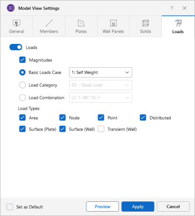
Access the graphical Model View Settings for loads by clicking the Model icon in the View Settings section of the View ribbon and selecting the Loads tab shown below.
Click on image to enlarge it
The Loads tab lets you specify that loads are to be displayed graphically, or that they are not to be shown at all.
Click the Loads slider to not display the loads in the model at all.
Check Magnitudesto display the numerical magnitude of the loads. You can specify that the loads be drawn as Basic Load Cases, Load Categories or Load Combinations by selecting the corresponding radio button. The load types to be displayed can be selected by checking the corresponding boxes.
Once you set the Model View Settings for loads, you can then run through all of the load cases, load categories or load combinations by choosing them from the drop down list at the top of the 3D View.

