Plates
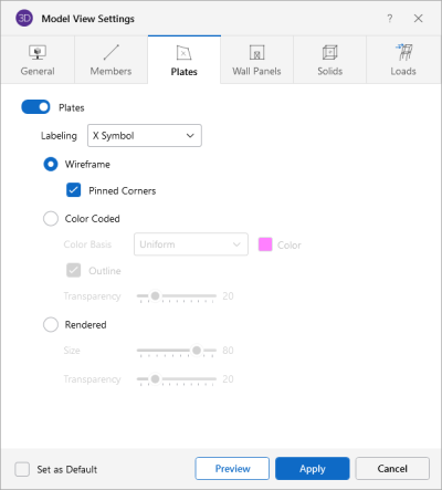
Access the graphical Model View Settings for plates
by clicking the Model icon in the View Settings section of the View ribbon and
selecting the Plates tab shown below.
Click on image to enlarge it
This tab lets you specify
that plates are to be drawn as wireframe, color coded,
or rendered elements, or that they are not to be shown at all.
Click the Plates slider to not display the plates in the model at all.
When the Wireframe option is selected,
you can include information on the plates when plotted. The Labeling drop down
list provides the choices you have as to what information will be displayed
on each plate, such as the plate label, material, thickness, or
the plate local axes. The wireframe option also allows you to display plate Pinned Corner conditions.
When the Color Coded option is selected, plates are plotted with different colors that
are mapped in a key shown in the upper right corner of the model view. You can
color the plates by material set or specify a uniform color for all
plates. You can toggle the Outline of the plates on and off. The color coded plates
themselves may be presented with varying Transparency
with 100% transparency meaning completely see through and 0% indicating completely solid.
When the Rendered option
is selected, true to scale representations of the plates are drawn with thickness.
You can also display the rendered plates at a percentage of their Size. This is useful in understanding orientation and connectivity in complex
views as shown below.
The Transparency setting described above for Color Coded plates also applies to Rendered plates.
Note: You can make any model view settings the default start-up settings. See
Set as Default - checkbox for more information on this feature.
