Loads - Area Loads
Area loads are loads that are applied to a planar area and automatically attributed to the members in that plane. This gives you the ability to model the loading effects on a membrane, such as live load on a deck system or wind on a curtain wall, without adding unwanted stiffness to the model. (To model load and stiffness You can use plate shell elements loaded with surface loads.)
The area loads are defined by polygons of three or four sides. The area loads can be uniform or tapered. They may be assigned a direction for one-way span situations, considered as two-way membranes that transfer load in all directions, or be assigned with an "Open Structure" load distribution which will apply loads to members based solely on their projected surface area. The loads from the area are assigned to the nearest members, not to plates.
-
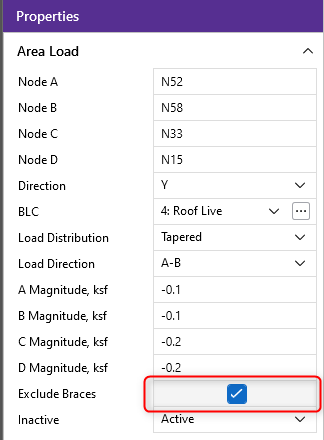
By default, area loads are not assigned to Vbraces, Hbraces, Tension-only, Compression-only, and Euler Buckling members. If you want to include them, you can uncheck the "Exclude Braces" checkbox for that area load, which will be discussed in the later sections.
- The
-
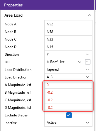
The magnitudes of the tapered area load must be coplanar. Program marks the invalid magnitudes in red in Property Panel and Member Area Loads spreadsheet, which will be discussed in later sections.
Draw Area Loads
![]()
Click on image to enlarge it
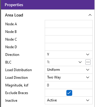
To apply area loads to members enter the load direction and magnitude. Make sure that you are careful to enter the correct BLC number that you want the loads assigned to.
Apply Member Area Loads
- If there is not a model view already open then go to the View tab and select the Open 3D Views button to open a new view.
- Go to the Home ribbon.
- In the ‘Draw Loads’ section click the Area icon.
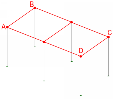
- Click on four nodes to define the area. For three sided areas click on the last node twice.
- You can also specify or edit area loads in the
- You can undo any mistakes by clicking the
 Undo button in the Quick Access toolbar.
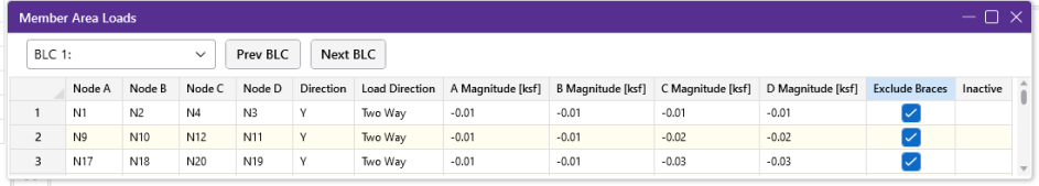
Member Area Loads Spreadsheet
The ![]() Member Area Loads or by clicking the Member Area Loads button in the Data Entry Panel
Member Area Loads or by clicking the Member Area Loads button in the Data Entry Panel
When you open this spreadsheet, you can view only one basic load case at a time. Use the drop down list or the
 button
The first four columns contain the
The next four columns hold the load magnitude in four different nodes. Notice area load supports both uniform and tapered loads.
The Exclude Braces column allows you to include or exclude certain members in the area load attribution, including Vbraces, Hbraces, Tension-only, Compression-only, and Euler Buckling members.
The last column allows you to set the specified load as an "Active" load that will be considered for the analysis, or an "Inactive" load that will not be included in the analysis.
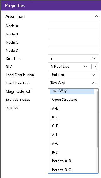
Member Area Load Direction
The direction code indicates the direction of application for the area load. The following directions are available:
Global loads are applied without being modified for projection. For example, a global Y-direction load of 1 ksf applied to an inclined plane with an area of 10 sq.ft. generates a total force of 10 kips, no matter what the incline is.
Projected loads, on the other hand, are applied in the global directions, but their actual magnitude is influenced by the planar orientation. The load is applied to the projected area of the element that is perpendicular to the load.
For example, a "PY" direction load is a projected load applied in the global Y direction. The actual magnitude of the load is the entered magnitude reduced by the ratio A/Axz. "A" is the actual area of the element and Axz is the element's projected area on the X-Z plane, which is always less than or equal to the actual area. See the following figure:
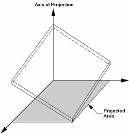
If the "Axis of Projection" in the figure is the Y-axis, then the shaded area is the total element area "projected" onto the plane perpendicular to the Y-axis (which happens to be the X-Z plane). The total load generated is equal to the input magnitude applied to the projected area. The generated load is then applied to the whole area, so the generated load magnitude is reduced accordingly.
For additional advice on this topic, please see the RISA Tips & Tricks website: www.risa.com/post/support. Type in Search keywords: Projected Loads.
Area Load Distribution
The Load Direction of the area load determines which members "support" the area load you define. You may choose between three main load direction options: two-way, one-way, or open structure. Below we will explain each of the main options. Next, you can choose to use uniform or tapered area load for Load Distribution option. The general concept of calculating loads attributed to supporting members is the same for uniform or tapered load. One thing to note is that if you use tapered load, you need to make sure the load magnitudes at those four nodes will be coplanar. If your input magnitudes failed in the coplanar check, program will use red font to remind users:
Two Way
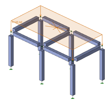
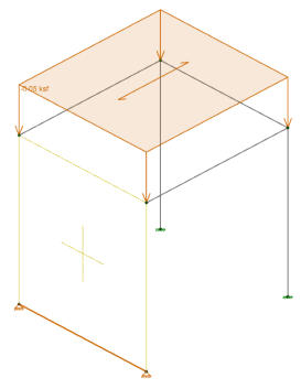
Two way area load distribution is analogous to how load travels through a two-way slab. Load will be distributed to the nearest member, regardless of direction. When a two-way area load is drawn there will be a star pattern shown to verify that load will go out in all directions. Here is an example model of a two-way slab with an area load:
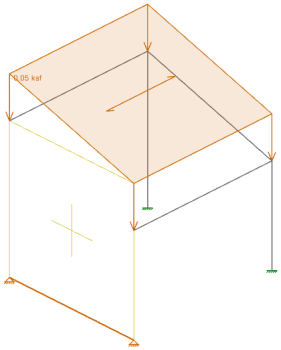
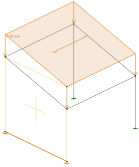
At solution, we can view how this load was applied by viewing the appropriate transient Basic Load Case:
![]()
![]()
Here we can directly see how the load was applied. See the Area Load Attribution section for more information.
One Way
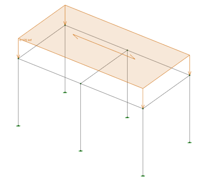
For a one-way distribution, you are asking the program to distribute loads in a single direction. There are multiple one-way options that all depend on the order that you click to create your area load. All options from A-B to Perpendicular to B-D are one way options. The A-B option means that the load will span one-way in a parallel direction to the first two corners of the area load (the A and B corners). Below is an image of what a B-C one-way area load distribution would look like:
![]()
For odd geometries the "Perpendicular..." options may be necessary to get the load distribution you are looking for.
Open Structure
As a third option, You can elect for the load to be distributed as an "Open Structure." This option applies the area load to each member based solely on the projected surface area (in the direction of the loading) of that member. The "Open Structure" distribution option is generally intended for open/lattice type structures for which a wind pressure is acting uniformly on all the exposed structural surfaces of the structure. The program will distribute the area load to the members as member distributed loads calculated as the area load magnitude multiplied by the face of the member perpendicular to the direction of the "Open Structure" load. Below is an example of the calculation for the "Open Structure" attribution:
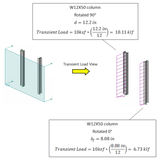
- The "Open Structure" load distribution option applies load to the members in the plane of the applied load as well as the members in the structure in-front of or behind that plane.
- Currently the "Open Structure" option does not take shielding into account for members behind other members.
-
The example above shows a uniform open structure area load example, if you use a tapered load, the transient load on the member could be tapered line load.
For additional advice on this topic, please see the RISA Tips & Tricks webpage at risa.com/post/support. Type in Search keywords: Member Area Load.
Area Loads and Wall Panels
Wall panels can now accept area loads as well. This, however, will only occur at the tops of walls and at diaphragm locations. If there is an area load applied at the top of a wall or where there is a diaphragm applied, then the wall panel will receive area load in the same way as a member.
![]()
This, however, will not work if the area load is not applied at the top of the wall, or there is no diaphragm defined where the area load intersects the wall panel. In this case no load will be applied to the wall. All of the load will go in the opposite direction.
![]()
You can force area loads to attribute to walls even if there is not a diaphragm at that elevation. This can be done by drawing in a "dummy" member or ledger beam at the same location as the wall. This member will receive area load like any other member, but should then transfer its load directly into the wall.
![]()
Area Load Attribution
Meshing
The program takes the area loads defined by you and breaks the loads down into finite "pieces". These pieces are broken down until the side dimension of the "piece" is less than that defined in
For additional advice on this topic, please see the RISA Tips & Tricks webpage at risa.com/post/support. Type in Search keywords: Verify Area Loads.
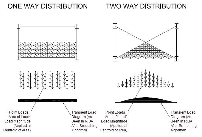
One way Attribution
One-way areas are attributed in the span direction based on the assumption of a simply supported deck. Each point load "piece" is attributed to supporting members based on the ratio of the distance of that member compared to the total deck span at that location. If there is no member in that direction then the load is attributed as a two-way load.
Two Way Attribution
Two-way areas are attributed to the members in all 4 directions based on an extension of a simply supported deck. Each point load "piece" is attributed to the members based on the ratio of the distance of that member compared to the distance of that point from the other members as shown in the image below:
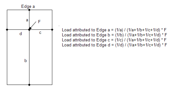
This results in a load distribution that agrees very closely with traditional hand calc methods.
Exclude Braces Option
By default, area load attribution does not include "brace-type" members, e.g., Vbraces, Hbraces, Tension-only, Compression-only, and Euler Buckling members. However, if users want to include the "brace-type" members in the load attribution, you can uncheck the "Exclude Braces" checkbox for that area load:
Transient Area Loads
After solution, the resulting distribution of the area load is stored in the first available basic load case with “BLC # Transient Area Loads” as the description. They can be viewed graphically or in the spreadsheets as a basic load case. These loads are transient which means they are only a result of the area load and will be deleted when the results are cleared and re-determined each time you solve the model. The only purpose of these transient BLC's is to let you view the exact load attribution created by the program.
![]()
- Members that are designated as Tension Only, Compression Only, or Euler Buckling will not receive any load during the Area Load Attribution.
- Members that are designated with a member type of VBRACE or HBRACE will not receive any load during the Area Load Attribution.
You can disconnect the attributed loads and take control of them by assigning a category to the automatically created basic load case. The original area loads will be left as they were so a subsequent solution will produce another distribution of loads that are a result of the defined area loads.
Solution Speed
Note that the area load algorithm used by RISA-3D is very versatile in that it can work in any of the global directions in a three dimensional model, so that it can be used for vertical dead or live load modeling as well as wind loads. But it can add a fair amount to the analysis time when small mesh sizes are used with large models. Sometimes a small mesh is necessary to get the desired accuracy for the area load attribution.