Stability
Instabilities occur whenever a
With that one statement you can understand and resolve any instability problem. Instabilities are easy to understand and easy to fix. The next section explains what RISA-3D does with instabilities. The following sections provide some simple examples of instabilities and their resolution.
For additional advice on this topic, please see the RISA Tips & Tricks webpage at risa.com/post/support. Type in Search keywords: Instabilities.
Instability Procedure
Because many instabilities are inconsequential to the results yet they prevent a solution RISA-3D locks them as they are discovered and proceeds with the solution. This locking is a boundary condition that removes the degree of freedom from the solution. A reaction (if any) is not calculated and that is one of the dangers of ignoring instabilities. See Testing Instabilities to learn how to test if an instability is affecting the results.
At the end of the solution you will be notified that

Click on image to enlarge it
Instability Causes
Common causes of instabilities are briefly mentioned here and then highlighted in the following examples.
Member End Releases – Boundary Conditions
Overuse of member end releases and/or boundary conditions is by far
the most common cause of instability as shown in the examples below. The solution is to either remove a member end release or change a boundary
condition so that the
Unconnected Elements
Flexible Elements
Members or plates with relatively small properties such as a long member with a moment of inertia of 1.0 in4 can cause instabilities. This is usually not a problem unless the members are not used properly.
Instability Examples
These simple examples are provided to directly address the common scenarios that occur in structural modeling. You will notice a recurring theme so once you understand one or two of them you will have a handle on the causes and resolutions for most instabilities, including those in more complex models.
Remember the golden rule as you look at each example: A
Cantilever Beam/Column
If a member end release is specified at the free end of a cantilever
the
Cause: Specifying a member release at the free end of a cantilever member.
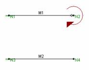
Resolution: Remove the member end release.
If the member is not released from the
Column at a Support
If a pinned column base is modeled with a pinned boundary condition
AND a member end release at the base of the column the
Cause: Specifying a pinned boundary condition AND a member release.
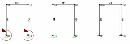
Resolution: Either remove the member end release or specify a fixed boundary condition. Do not do both unless you want a fixed column base that resists moment.
If the member is not released from the
If instead the boundary is specified as fixed then the boundary provides
resistance to the
Simply Supported Beam
If a pinned beam end is modeled with a pinned boundary condition AND
a member end release the
Cause: Specifying a pinned boundary condition AND a member release.
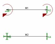
Resolution: Either remove the member end release or specify a fixed boundary condition. Do not do both unless you want a fixed member end that resists moment.
If the member is not released from the
If instead the boundary is specified as fixed then the boundary provides
resistance to the
Beam-Column Connection
If a pinned beam/column connection is modeled with
a released column end AND a released beam end the
Cause: Specifying a released column end AND a released beam end.
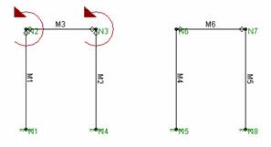
Resolution: Either remove the column end release or the beam end release. Do not do both unless you want a fixed connection that resists moment.
If the column is not released from the
Simple Truss
If a truss panel point is modeled with releases at the ends of EVERY
member connecting to that point the
Cause: Specifying all members with released ends.
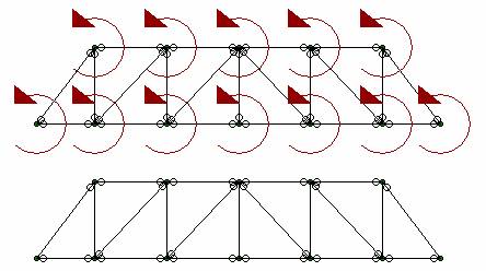
Resolution: Either remove one
end release or add a rotational boundary condition at each
If one member end is not released from each
You can also solve the problem with a rotational boundary condition
at each
2D Models
If you are solving a 2D model defined in the XY plane and you're only interested in the planar action, you could enter "ALL" and put an "F" (for Fixed) for Z translation, X Rotation and Y Rotation. See the following figure:

Click on image to enlarge it
There is a 2D Mode button which can quickly add Fixed boundary conditions to all nodes in the Z translation:

Click on image to enlarge it
Unconnected Elements
If a
Cause: Unconnected elements. The portal frame is not connected to the plate elements because the bottoms of the columns do not fall on plate corners. The plates are stable however the portal frame is not.
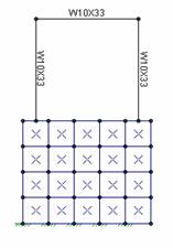
Resolution: For beam models, run the Model Merge feature. For plate models redefine the mesh so that plates are connected at their corners. Model merge will not solve problems caused by lack of plate continuity.
3D Models
For three-dimensional models, torsional instabilities are not uncommon. A "torsional" instability is where a member, or a series of members, is free to spin about its centerline (local x) axis. This diagram illustrates such a situation:
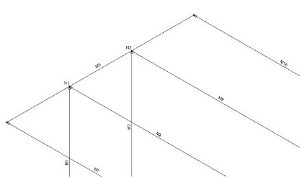
The member M3 as a whole is unstable because
there is nothing to restrain it from spinning in torsion. At
Another example of a potential local instability
is X-bracing with a center
Testing Instabilities
Although some can be ignored, keep in mind that not all instabilities are necessarily inconsequential. Look at the following model:
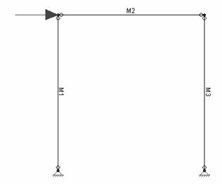
This is an example of a single bent frame that is laterally unstable. To obtain a solution the lateral direction would be locked and a solution obtained, though not a correct one. The warning message may be annoying if you know the instabilities being locked are of no consequence, but there won't be any surprises.
The best way to test whether an instability is inconsequential or not
is to apply a Reaction to the