This section is specific to column checks for moment connections or shear connections with axial force.
This section applies to flange forces on moment connections only. Please see Required Flange Forces to see how RISAConnection calculates the flange forces when moment and axial loads are present.
Shear connections are assumed to carry all axial load through the connecting elements.
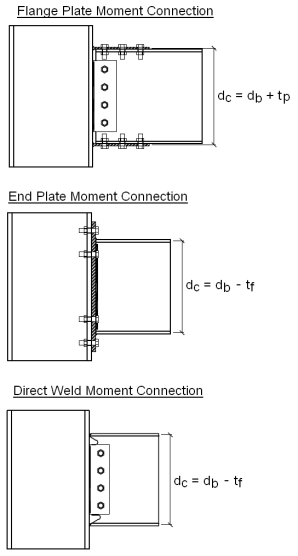
The depth of the moment arm between flange forces (dc) is described below. RISAConnection assumes these to be applied at the centroid of the beam flange (for End Plate and Direct Weld Moment Connections) or that of the flange plates (for Flange Plate Moment Connections).
For many of these checks where these forces are transferred into the column defines which equation you use in the specification. RISAConnection defines these locations for each moment connection type as:
Note that we always assume the top flange is in compression for these moment connections, or we assume that the moment can be reversed.
The AISC 360-10 specification specifies k as the distance from outer face of the column flange to the web toe of the fillet. Table 1-1 from the 14th Edition Steel Manual list both a kdet and a kdes value. RISAConnection assumes k = kdes for this value.
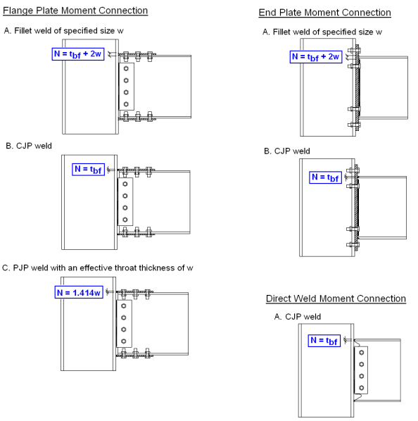
N is defined as the bearing length of the applied force. Therefore this value differs based on the weld type specified to connect the beam flange to the column or end plate. RISAConnection uses the following assumptions when calculating this value:
This column flange bending capacity check is calculated per section J10.1 of the AISC 360-10 specification. Expand this section of the design report and RISAConnection will provide you with the exact equation, code reference, listed variables, as well as the code check value and pass or failure notification.
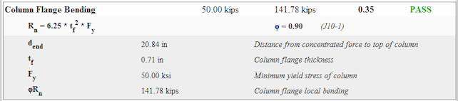
Per section J10.1 of the AISC 360-10 specification, the available strength shall be reduced if the force application is at a distance less than 10*tf from the end of the member. This can be addressed in RISAConnection by adjusting the user input Top Column Distance in the Loading section of Connection Properties. Please see the Concentrated Force Location section for more information on how this location is calculated.
For instance, if Concentrated Force Location < 10*tf, RISAConnection will reduce Rn by 0.5.
Note:
This moment capacity check applies to the Beam Flange Plate Moment Connection. This check is calculated per section J10.1 of the AISC 360-10 specification. Expand this section of the design report and RISAConnection will provide you with the exact equation, code reference, listed variables, as well as the code check value and pass or failure notification. See the Moment Arm section for more information on how this value is calculated.
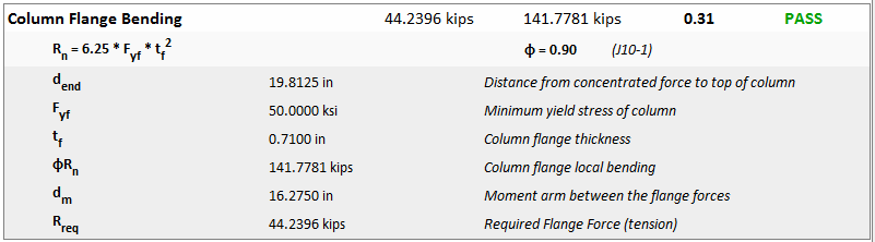
Per section J10.1 of the AISC 360-10 specification, the available strength shall be reduced if the force application is at a distance less than 10*tf from the end of the member. This can be addressed in RISAConnection by adjusting the user input Top Column Distance in the Loading section of Connection Properties. Please see the Concentrated Force Location section for more information on how this location is calculated.
For instance, if Concentrated Force Location < 10*tf, RISAConnection will reduce Rn by 0.5.
This check applies to the End Plate Moment Connection. This check is calculated per Section 3.12.15 and Table 3.4 of the AISC Steel Design Guide 4 (Second Edition). Expand this section of the design report and RISAConnection will provide you with the exact equation, code reference, listed variables, as well as the code check value and pass or failure notification.
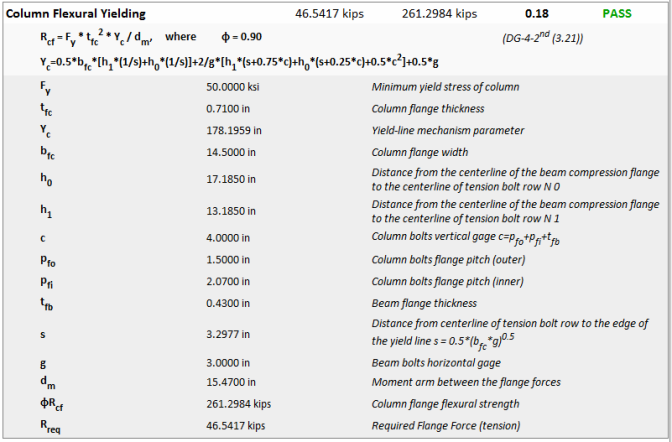
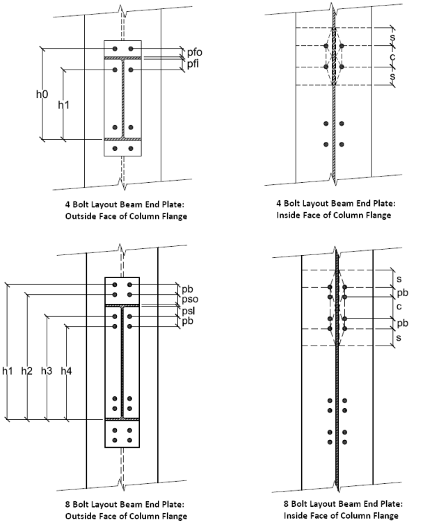
This check contains some complicated geometry to approximate the yield line pattern. Below are graphical explanations of some of the more complicated terms:
Some End Plate connections do not have column yield line formulas specifically listed in the design guides.
Note:
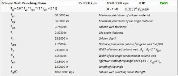
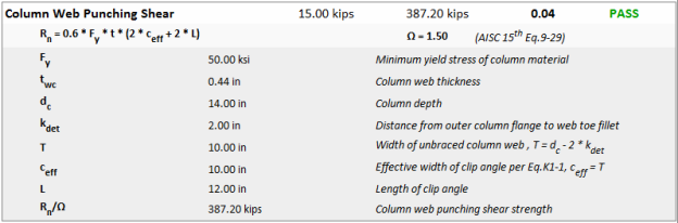
The column web punching shear capacity check is calculated per the AISC 15th edition Steel Design Manual section on Plate Elements Subjected to Out-of-Plane Loads on page 9-14. Expand this section of the design report and RISAConnection will provide you with the exact equation, code reference, listed variables, as well as the code check value and pass or failure notification. This check is included for beam to column shear connections with any (compression or tension) axial load.
Unfortunately older versions of the AISC Steel Design Manual do not give direction on out of plane checks on a Wide Flange column web, but you may opt to check these per the AISC 15th edition requirements by selecting the Include AISC 15th Out of Plane Web Checks check-box on the Solution tab of the (Global) Model Settings.
Note:
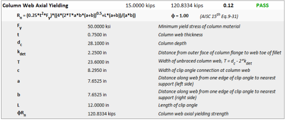
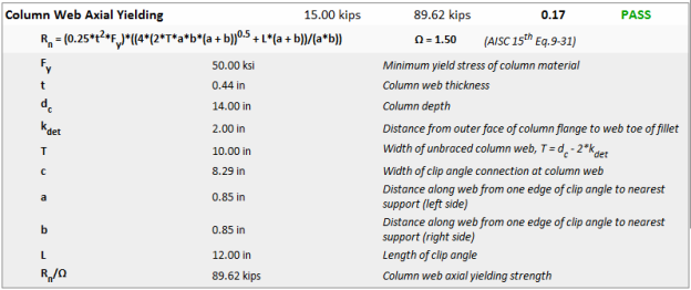
The column web axial yield capacity check is calculated per the AISC 15th edition Steel Design Manual equation (9-31) on page 9-16. Expand this section of the design report and RISAConnection will provide you with the exact equation, code reference, listed variables, as well as the code check value and pass or failure notification. This check is included for beam to column shear connections with any (compression or tension) axial load.
Unfortunately older versions of the AISC Steel Design Manual do not give direction on out of plane checks on a Wide Flange column web, but you may opt to check these per the AISC 15th edition requirements by selecting the Include AISC 15th Out of Plane Web Checks check-box on the Solution tab of the (Global) Model Settings.
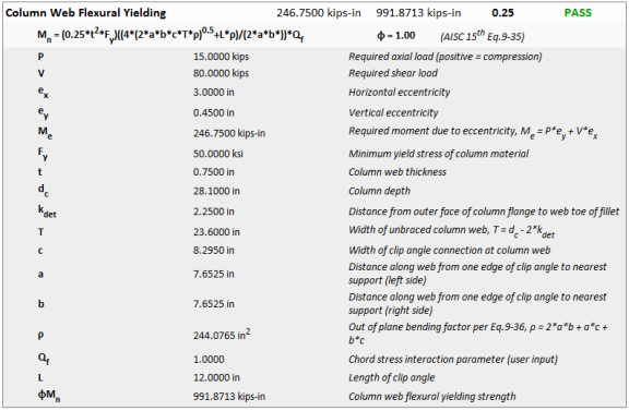
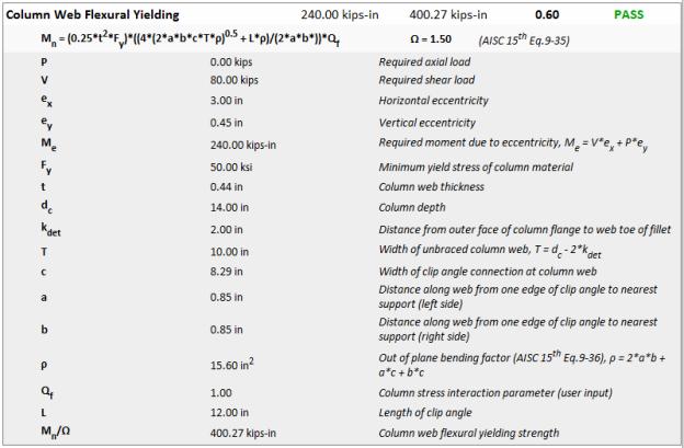
The column web flexural yield capacity check is calculated per the AISC 15th edition Steel Design Manual equation (9-35) on page 9-17. Expand this section of the design report and RISAConnection will provide you with the exact equation, code reference, listed variables, as well as the code check value and pass or failure notification. This check is included for any shear connection with moment at the column due to eccentricity in the shear connection.
Unfortunately older versions of the AISC Steel Design Manual do not give direction on out of plane checks on a Wide Flange column web, but you may opt to check these per the AISC 15th edition requirements by selecting the Include AISC 15th Out of Plane Web Checks check-box on the Solution tab of the (Global) Model Settings.
Note:
This column web yielding capacity check is calculated per section J10.2 of the AISC 360-10 specification for Wide Flange Columns with beams connected to the column flange. Expand this section of the design report and RISAConnection will provide you with the exact equation, code reference, listed variables, as well as the code check value and pass or failure notification.
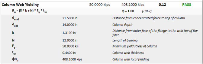
Per section J10.2 of the AISC 360-10 specification, there are two equations that apply to this check: J10-2 and J10-3. RISAConnection calculates the Concentrated Force Location to see which of these equations applies. Please see the Concentrated Force Location section for more information on how this location is calculated.
Therefore, if the Concentrated Force Location > dbeam, RISAConnection will use equation J10-2. If the Concentrated Force Location ≤ dbeam, RISAConnection will use equation J10-3.
Note:
This check applies to Beam Flange Moment Connections and End Plate Moment Connections for Wide Flange Columns with beams connected to the column flange but is calculated slightly differently for each type of check.
For Flange Plate Moment Connections, this check is calculated per section J10.2 of the AISC 360-10 specification. Expand this section of the design report and RISAConnection will provide you with the exact equation, code reference, listed variables, as well as the code check value and pass or failure notification. See the Moment Arm section for more information on how this value is calculated.
For End Plate Moment Connections, section J10.2 of the AISC 360-10 specification is not as clear. Therefore, RISAConnection instead references the AISC Design Guide 4, 2nd Edition which references the AISC 2nd Edition LRFD code.
This code has a much clearer reference to End Plate Moment connections and assumes a larger projection, as shown in the image below.
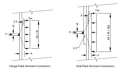
Expand this section of the design report and RISAConnection will provide you with the exact equation, code reference, listed variables, as well as the code check value and pass or failure notification. See the Moment Arm section for more information on how this value is calculated.
Note:
Per section J10.2 of theAISC 360-10 specification, there are two equations that apply to this check: J10-2 and J10-3. RISAConnection calculates the Concentrated Force Location to see which of these equations applies. Please see the Concentrated Force Location section for more information on how this location is calculated.
Therefore, if the Concentrated Force Location > dbeam, RISAConnection will use equation J10-2. If the Concentrated Force Location ≤ dbeam, RISAConnection will use equation J10-3.
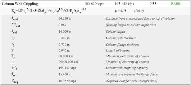
This column web crippling capacity check is calculated per section J10.3 of the AISC 360-10 specification. Expand this section of the design report and RISAConnection will provide you with the exact equation, code reference, listed variables, as well as the code check value and pass or failure notification.
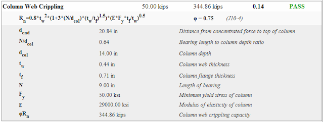
There are three equations that come into play for this check. When the concentrated compressive force to be resisted is applied at a distance from the member end that is greater than or equal to dcol/2 use equation J10-4. If this distance is less than dcol/2, then use either J10-5a or J10-5b. Please see the Concentrated Force Location section for more information on how this location is calculated.
The differentiation between equations J10-5a and J10-5b depends on the ratio of bearing length to overall depth of the beam (N/d). See the Column Moment Checks topic for information on calculating N. If N/d <= 0.2, then equation J10-5a is used. If N/d > 0.2, then equation J10-5b is used.
The program will perform all of these dimensional checks and use the appropriate equation automatically.
Note:
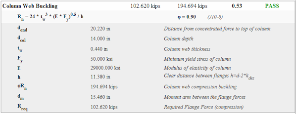
Web crippling is local buckling that occurs when the web is slender (i.e. h/tw is large). The behavior is more restrained when the point load is applied away from the ends of the member. Because of this there are separate equations for when a concentrated transverse load is located near or away from the end of the member. This limit state is to be checked at each location where a concentrated force is applied transverse to the axis of a member.
The AISC 360-10 Specification section J10.3 gives the capacity equations to consider column web crippling.
There are three equations that come into play for this check. When the concentrated compressive force to be resisted is applied at a distance from the member end that is greater than or equal to dcol/2 use equation J10-4. If this distance is less than dcol/2, then use either J10-5a or J10-5b. This location where this compressive force occurs is defined earlier in this topic.
The differentiation between equations J10-5a and J10-5b depends on the ratio of bearing length to overall depth of the beam (N/d). See information earlier in this topic for information on calculating N. If N/d <= 0.2, then equation J10-5a is used. If N/d > 0.2, then equation J10-5b is used.
The program will perform all of these dimensional checks and use the appropriate equation automatically.
Note:
This check applies to both Beam Flange Moment Connections and End Plate Moment Connections. This check is calculated per section J10.5 of the AISC 360-10 specification. Expand this section of the design report and RISAConnection will provide you with the exact equation, code reference, listed variables, as well as the code check value and pass or failure notification. See the Moment Arm section for more information on how this value is calculated.
Note:
Per section J10.5 of the AISC 360-10 specification, the available strength shall be reduced by 50% if the force application is at a distance less than half the depth of the column. RISAConnection refers to this value as the Concentrated Force Location and is calculated per the user input Top Column Distance. Please see the Concentrated Force Location section for more information on how this location is calculated.
For instance, if Concentrated Force Location < 0.5*dbeam, RISAConnection will reduce Rn by 0.5.
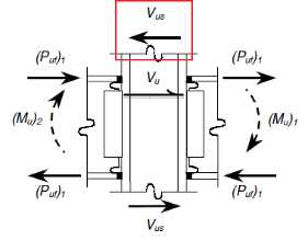
Column web panel zone shear is a phenomenon that occurs when double-concentrated forces are applied to a member. A moment connection's beam flange forces creates these double concentrated forces.
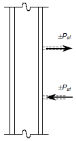
These forces cause a shear to the web panel zone that we are checking here.
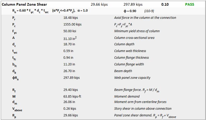
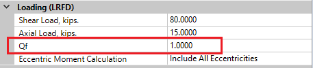
There are four equations from the AISC 360-10 specification that are used, equations J10-9, J10-10, J10-11 and J10-12. The program assumes that the effect of panel-zone deformation on frame stability is not considered in the analysis, thus equations J10-11 and J10-12 are never used. Whether to use J10-9 or J10-10 depends on the axial force in the column at the location of the connection. This force is input in the Loading section. If this force is <= 0.4*Pc then J10-9 is used. If Pr > 0.4*Pc, then J10-10 is used.
Note:
The actual demand panel zone shear that occurs can be reduced by the story shear coming into the panel zone.
This story shear is also an input in the Loading section. If there is story shear, then the program calculates an Mequivas the design demand. This is a reduced demand based on a reduced panel zone shear due to this story shear. Because the code checks are based on converting the capacities into equivalent moment capacities, the same must be done for the moment demand in this case.
RISAConnection will take all of the inputs, perform the applicable checks and use the appropriate equation.
The AISC 15th (360-16) edition Steel Construction Manual introduced explicit out of plane checks for column web connections loaded out of plane. These checks are listed below. Older versions of the Steel Construction Manuals did not include direction for these checks, but RISAConnection will allow you to include the checks along with older codes if you select the "Include AISC 15th Out of Plane Web Checks" check box on the Solution tab of Project Settings.
The punching shear limit for a clip angle or end plate connection to a column web is checked per eqn (9-29) on page 9-14 of the 15th Edition Steel Construction Manual. For more detail see Column Web Punching Shear (Shear Connections).
Out of plane transverse loads on a column web are checked per eqn (9-31) on page 9-16 of the 15th Edition Steel Construction Manual. For more detail see Column Web Axial Yielding (Shear Connections to Column Web).
Out of plane moment loads on a column web are checked per eqn (9-35) on page 9-17 of the 15th Edition Steel Construction Manual. For more detail see Column Web Flexural Yielding (Shear Connections to Column Web).
Please see the section on HSS Checks for the details on similar out of plane checks for HSS connections.