These checks are specifically for coped beams. The checks apply under the following conditions:
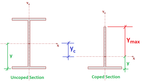
The Net Section Modulus is used in most of the strength calculations for coped beams. These are calculated automatically by the program based on the beam section properties and the depth and length of the cope as specified in the Assembly portion of the Connection Properties grid. These calculations should closely match the values reported in AISC 14th Edition Manual Table 9-2.
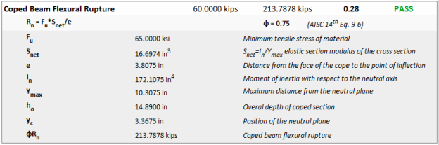
The nominal Flexural Rupture Strength of the member is determined by multiplying the ultimate stress of the beam material by the net section modulus of the member. Since rupture is a less ductile failure mode, a phi factor of 0.75 and an Omega of 2.0 are used to determine the design strength for this failure state.
The geometric variables include:

This code check procedure is based on guidelines given in the AISC 14th Edition Manual. Specifically the topic on Connecting Elements Subject to Flexure, which can be found on page 9-6. It is also explicitly outlines in the AISC 13th Edition Manual on page 9-6.
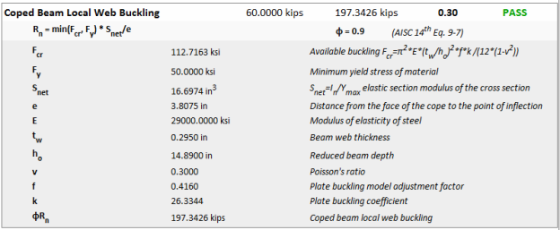
The webs of coped beams have reduced strength to resist location buckling because they are not stiffened by the coped flange. This failure state is determined by multiplying the critical buckling stress by the net section modulus. This buckling is judged to be a more ductile limit state than rupture and has, therefore, been given a phi factor of 0.90 and an Omega factor of 1.67.
The geometric variables include:
These code check procedure is based on guidelines given in the AISC 14th Edition Manual. Specifically the topic on Connecting Elements Subject to Flexure (item #1), which can be found on page 9-7.
Flexural yielding of the beam is not considered as it's own code check. However, the critical buckling stress Fcr from the Local Buckling Strength calculation is limited to a maximum value of Fy. Therefore, the web buckling strength calculations effectively checks the flexural yielding limit state as well.
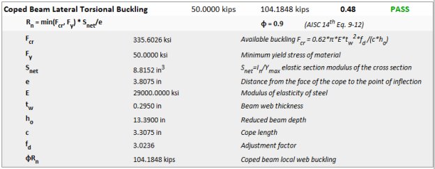
Most of the time the beam will be coped only at the top flange. However, the program calculations will take into account the more unusual case when both flanges are coped. The equations used to calculate the critical buckling stress will be based on the lateral-torsional buckling limit state rather than web local buckling.
The geometric variables include:
This code check procedure is based on guidelines given in the AISC 14th Edition Manual. Specifically the topic on Connecting Elements Subject to Flexure (item #2), which can be found on page 9-8.
Flexural yielding of the beam is not considered as it's own code check. However, the critical buckling stress Fcr from the Lateral-Torsional Buckling Strength calculation is limited to a maximum value of Fy. Therefore, the web buckling strength calculations effectively checks the flexural yielding limit state as well.