These checks are unique to certain types of moment connections. Moment checks that are standard bolt and material checks, see the Bolt & Material Checks topic. For weld information, see the Weld Checks topic.
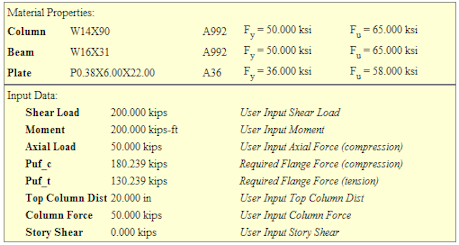
All moment connections can resist axial, shear, and moment forces. The axial and moment force is converted into a Required Flange Force (Tension and Compression) which is reported at the top of the results Report. This value (sometimes tension, sometimes compression) is then compared to the Available capacity of each limit state in the Unity Check value.
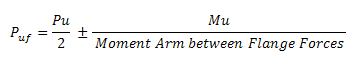
The Required Flange Force is calculated as:
These checks are specific only to end plate moment connections. There are several checks for plate failure in an end-plate moment connection. These checks are outlined below. All design procedures and equation references, unless otherwise noted, are taken from AISC Design Guide #4, 2nd Edition. In cases where bolt prying may affect the design, the prying effects are calculated per the procedure in AISC Design Guide #16.
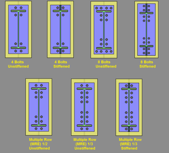
Currently the program can model any type of end plate connections described in the AISC design guides, plus an 8 bolt extended connection not specifically described in the design guides. The yield lines for this "8 Bolt (unstiffened)" connection are taken from Emmet Sumner's PhD thesis ("Unified Design of Extended End- Plate Moment Connections Subject to Cyclic Loading" June 17, 2003) which forms much of the basis for Design Guides 4 and 16. Specifically refer to the MRE 1/2 connection in this paper (section 4.4.4.7 and Figure 4.9) for the end plate yield lines. Similarly refer to the MRE 1/3 connections in Figures 4.10 and 4.11 for the end plate yield lines of the unstiffened and stiffened connections, respectively.
For flush end plate moment connections the grvalue is always assumed to be equal to 1.25 to limit the connection rotation at ultimate moment and allow the connection to qualify as a fully restrained moment connection.
Note
This check is calculated for the bolts in tension on the End Plate Moment Connection. Expand this section of the design report and RISAConnection will provide you with the exact equation, code reference, listed variables, as well as the code check value and pass or failure notification.
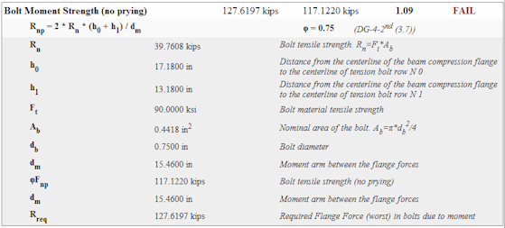
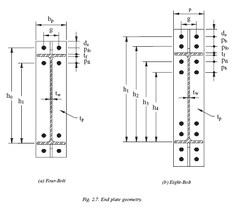
The moment capacity for this check is based on Bolt Tensile Strength from section J3.6 of the AISC 360-10 specification and the Bolt Tension Strength equations (3.7 and 3-8) from the AISC Steel Design Guide 4 (Second Edition). The variables are displayed graphically on page 15 of the Design Guide in Figure 2.7.
Note:
The Bolt Moment Strength check varies depending on whether there is prying force action or not. Therefore, the program reports this section to show the calculations which determined what Bolt Moment Strength check was used.
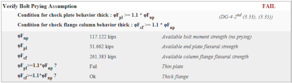
This check is covered in the AISC Design Guide #4 "Extended End-Plate Moment Connections", 2nd edition, Copyright 2003 in Section 3.3. We check both the end plate and the column flange for "thick" plate behavior.
Fnp - The no-prying bolt tension rupture strength, found in the Bolt Moment Strength check.
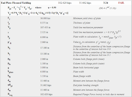
Fpl - The end plate bending strength, found in the End Plate Flexural Yielding check.
Fcf - The column flange flexural strength, found in the Column Flexural Yielding check.
For 8 bolt moment connections, if either these checks fail, then the no prying assumption is not valid. Thus, the connection will be said to "fail". IN reality, it may work fine, but the user would have to demonstrate how to manually consider prying for the bolt tension checks.
In order to prevent buckling of the stiffener plate, the stiffener plate thickness is checked per eqn (3.16) of the AISC Design Guide #4, 2nd Edition.
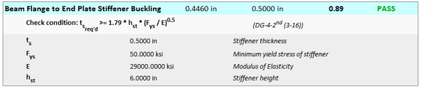
For flush end plate connections, no capacity checks are made on any stiffeners specified between the beam web and end plate.
Note:
The program uses the procedures and tables from the AISC design guides, to determine an end-plate bending strength, and a no-prying bolt tension rupture strength.
If the plate bending strength exceeds 110% of the bolt rupture strength then thick-plate behavior is confirmed and a code check is given based on the other failure modes of the connection. If the plate bending strength does not exceed 110% of the no prying bolt rupture strength, then the program will calculate bolt prying forces and connection capacity per the procedures given in Design Guide 16.
Note:
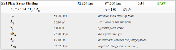
The extended portion of the end-plate is checked against shear yielding due to out-of-plane shear (the flange force of the beam). See Eqn 3.12.
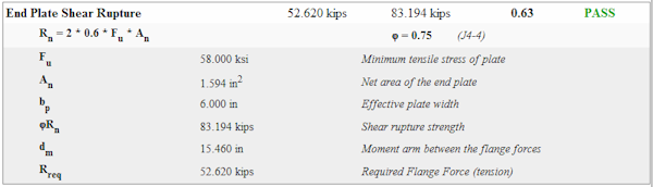
The extended portion of the end-plate is checked against shear rupture due to out-of-plane shear (the flange force of the beam). See Eqn 3.13.
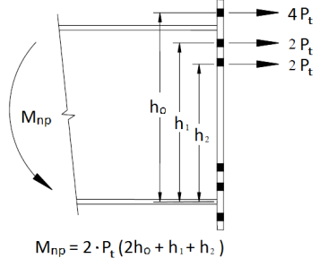
This bolt configuration cannot be found in either AISC design guide. However, the yield lines are identical to that shown for the MRE 1/2 configuration shown Design Guide 16. The moment strengths based on the bolts need only be modified by accounting for additional bolts at the top row as shown in the image below.
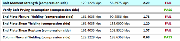
End Plate Moment Connections that are flush on both sides or extended on one side and flush on the other may have a different bolt configuration on the tension side of the connection than on the compression side. This changes the yield line patterns when the "compression" side of the connection goes into tension. This will generally happen when there is moment reversal, but can also occur for connections with have a significant axial tension force.
When this occurs, the output reports only report the limit states for the controlling side. To clearly identify when this situation occurs, the program flags the limit state with text that says "(compression side)" as shown in the image below:
RISAConnection always assumes that Flush End Plate moment connections will always be designed as Type 1 or Fully Restrained moment connections. That means that gr value is always applied to the design of the plate. This is done by increasing the demand force or moment associated with the end plate limit states.
Note:
When an axial force is added to a moment connection, it is assumed that this axial force is carried entirely by the flanges (Please seeRequired Flange Force). Therefore, the axial force will not affect the shear checks for the moment connection.
Note:
If the moment connection includes transverse column stiffeners and / or web doubler plates then additional design checks will be performed on these elements. Refer to the Stiffener Checks for Moment Connections topic for more information.
RISAConnection allows you to model both Direct Weld, Flange Plate Moment and Flange Plate Cap Plate Moment connections into the web of a wide flange column.
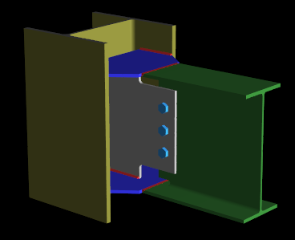
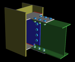
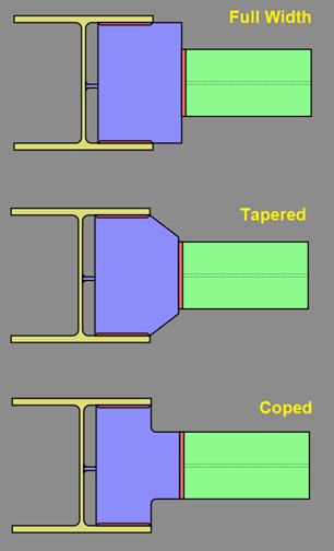
When you select this orientation, the program will automatically include Flange Plate stiffeners that connect to the beam flanges and the inside column flanges. The Flange Plates are assumed to always be welded to the inside flanges of the column. In the case of a cap plate, the cap plate may be welded to both the inside and outside flanges of the column. You may select a Full Width, Tapered, or Coped end that connects to the beam. The flange forces are then resisted by the flange plate weld strength at the column.
Note:
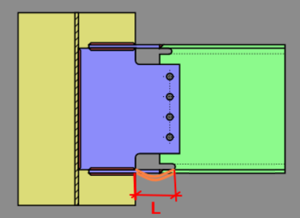
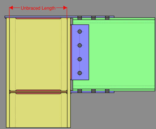
RISAConnection considers the full unbraced length of the compression flange in the Flange Plate Compression check. This is measured from the far edge of the weld access hole on the beam to the weld at the column flange.
RISAConnection considers the unbraced length of the cap plate in the Cap Plate Stiffener Compression check to be the clear distance between column flanges.
The cap plate acts as both a flange plate connected to the top of the beam flange and a transverse stiffener that is connected to the top of the column. The design force used for the cap plate is the beam flange force generated by the moment within the beam. The force developed within the top beam flange is transferred directly into the column through welds at the top of the column. Here are some general assumptions used by RISAConnection.
Guidance from the AISC Design Guide 24 is used for the connection checks for the continuous beam over column connection. The connection can support axial load onto the column (from the beam), strong axis bending moment (bending perpendicular to the beam’s length), and shear forces in either direction. Weak axis bending moment (bending parallel to the beam’s length) is not supported. Additional guidance from AISC Design Guide 4 and 16 are used when Design Guide 24 does not provide sufficient information.
Due to limited guidance for newer AISC codes from Design Guide 24; HSS column wall local checks (yielding and crippling) are completed using more conservative AISC equations. For AISC 15th edition, the yielding check is calculated per AISC J10-3 and the crippling check is calculated per AISC J10-5a.