The Vertical Brace Connections are intended for braces in the vertical plane, or as truss connections.
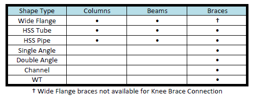
The following shape types are allowed:
Diagonal and Chevron braces can be designed as non-seismic (R=3) connection types or as part of an OCBF or SCBF Seismic System. For more information on seismic vertical brace design, see the Seismic Vertical Brace Connections topic.
Below is the list of current limitations for vertical brace design in RISAConnection.
Gusset plates for Vertical Diagonal Braces and Knee Braces can be rectangular or have tapered edges. There are two ways to model a tapered gusset plate: Cut Back or Custom Angle.
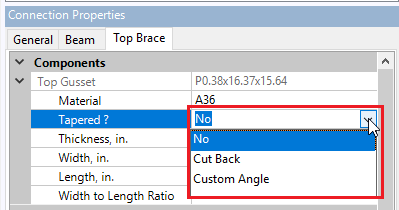
Cut Back
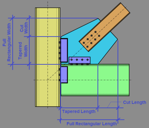
To enter a Cut Back taper, enter Cut Length and Cut Width dimensions to "cut back" the original rectangular gusset.
Custom Angle
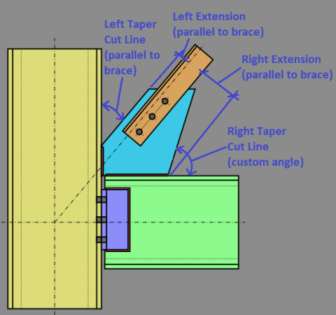
To enter a Custom Angle taper, enter Left and Right Side Cut Angles (from the vertical axis), and Left and Right Extensions to define the tapered shape. For ease of modeling, the Left and Right Cut Angles may be set equal to the brace angle or defined with a custom angle.
Note:
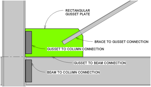
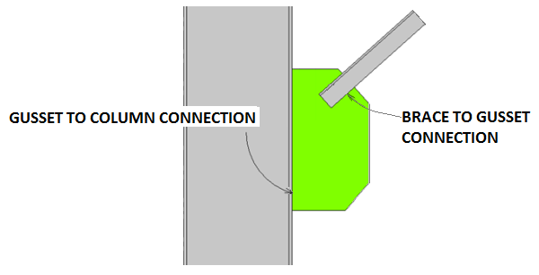
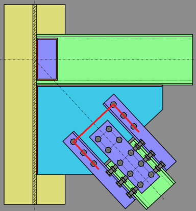
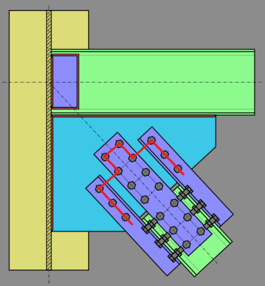
The diagonal brace configuration supports braces framing into a column above, below, or above and below the beam. Each Diagonal Brace Connection consists of four sub-connections, illustrated with an example below:
Note:
See below for more information on Gusset Plate design and connection eccentricity.
The program uses the Uniform Force Method to determine the distribution of forces within the gusset. This determines the forces on all of the sub-connections (i.e. Gusset to Beam) as well. For more information on this method see the AISC 14th Edition Manual, Page 13-3.
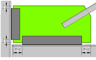
Under the Brace tab(s) on the Connection Properties grid, you can expand the Gusset section to set your desired Width to Length Ratio. The available options are shown below and your selection controls if your sub-connections will be designed for moment forces or not. The details for these options are shown below.
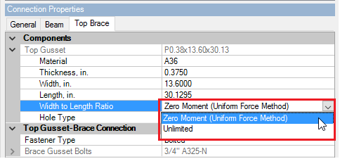
When you select the Zero Moment (Uniform Force Method) option, RISAConnection will automatically limit your gusset plate dimensions so equation (13-1) from the AISC 14th Edition is met. This ensures that the free-body diagram of each sub-connection remains moment-free.

The design forces on each sub-connection interface will then be designed per equations (13-2) through (13-6). Please see page 13-5 of the AISC 14th Edition for further details on these calculations.
When you select the Unlimited option, RISAConnection will not make any attempt to limit your connection geometry. This means that the sub-connection interfaces may be subject to moments due to eccentricities.
The calculation and distribution of these moments is determined according to the procedure outlined in the AISC 14th Edition Manual, Page 13-10.
Note:
For configurations which do not use concentric work points, you may define your eccentricity under the Assembly options on the General tab. When you do this, RISAConnection will automatically change your Width to Thickness Ratio analysis method to "Unlimited" so the connection can be designed for moment forces at the sub-connections.
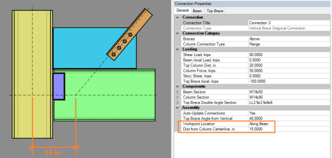
The moment force is determined according to brace eccentricity from the idealized brace line of action which runs through the beam-column intersection (15 inches in the above example).
RISAConnection accounts for this moment using a procedure discussed in Section 2.2.1.8 of the Handbook of Structural Steel Connection Design and Details, Second Edition, Akbar R. Tamboli. This procedure calculates horizontal and shear forces at the gusset-beam and gusset to column interfaces using the Uniform Force Method as if the connection had no eccentricity. The procedure then adds in a moment due to eccentricity and attributes that moment to the gusset-beam and gusset-column interface.
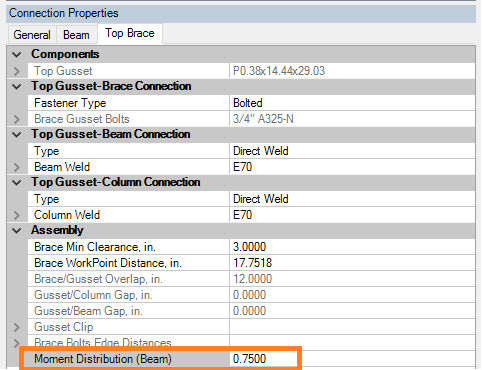
RISAConnection is not capable of determining how much of this moment is taken by the beam or the column, as that is a function of the rigidities of the gusset-beam connection and the gusset-column connection, respectively. This distribution is determined by a Moment Distribution Factor, which is user-entered in the Assembly properties on the Brace tab.
Note:
The total moments are determined at each sub-connection location based on the sum of the moments from gusset plate dimensions and the work point eccentricities. These moments can be accounted for in one of two ways:
The gusset will designed for moment using the procedures established for extended shear tab connections or extended clip angle connections. Both of which have had their design procedures adjusted to account for the potential presence of a large axial forces in addition to the expected shear force.
For Diagonal Brace Connections the beam is assumed to be pinned to the column. Therefore, no consideration is made for distortion / deformation relationships which result in frame action. For more information on these considerations see Section 2.2.1.5 of the Handbook of Structural Steel Connection Design and Details, Second Edition, Akbar R. Tamboli.
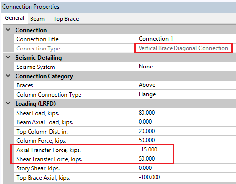
By default RISAConnection designs diagonal brace connections as simple 2D connections without any interaction with braces on the other side of the column, or horizontal braces framing into the beam/column joint. However, you may also input transfer forces (axial and shear) to represent the load from other elements that are on the same side of the connection such as horizontal braces at the beam/column sub-connection. Note that transfer forces from elements on the opposing side of the column are not currently supported at this time.
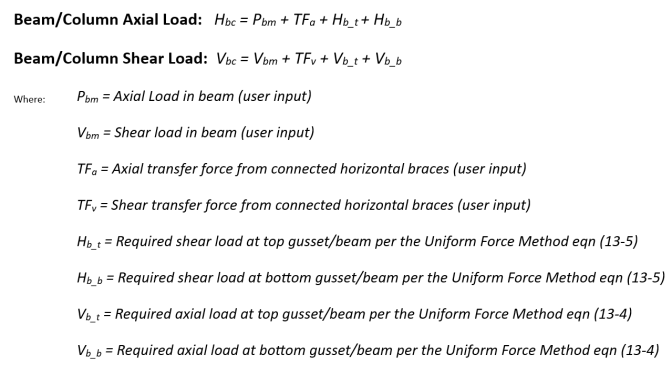
Traditionally, the Uniform Force Method (and the Unlimited Method) has calculated the required shear and axial forces using the simplified (2D assumption) equations on the middle of page 13-5 of the AISC 14th edition Steel Design Manual. RISAConnection extrapolates this using simple statics to also include the Axial Transfer Load and the Shear Transfer Load. The axial transfer force is defined as the component (in plane of the connection) from the connected horizontal braces. The Shear Transfer Force is defined as the required shear force from connected horizontal braces.
The chevron brace configuration supports two braces framing into a beam from opposite directions. Each Chevron Brace Connection consists of three sub-connections, illustrated below:
![]()
Note:
See below for more information on Gusset Plate design and connection eccentricity.
The program uses statics to determine the distribution of forces within the gusset. Gusset design is assumed to be controlled at one of two section cuts, as shown in the illustration below:
![]()
Section a-a
The shear and axial force at section a-a are calculated as the net horizontal and vertical forces from the braces. The in-plane moment at section a-a is calculated as the net moment induced by both braces. The moment induced by each brace is calculated as the force in the brace, multiplied by the distance between the center of the beam-gusset interface and the nearest point along the brace's centerline (shown dashed above).
Section b-b
The shear (V'), axial force (N'), and in-plane moment (M') at section b-b are calculated using the method of sections (statics). The derivations are shown below.
![]()
![]()
Note:
Similar to the Chevron brace connection, the program uses statics to determine the distribution of forces within the gusset. However in contrast to the chevron brace connection where a single section b-b cut is taken at the center of the gusset, several section b-b cuts are taken at the shear tab for the extended shear tab connection and the cut producing the highest largest code check is used. The reasoning for this is because the addition of a beam axial force into the shear tab between two braces produces more fluctuation of the resulting forces depending on where the section b-b cut is taken.
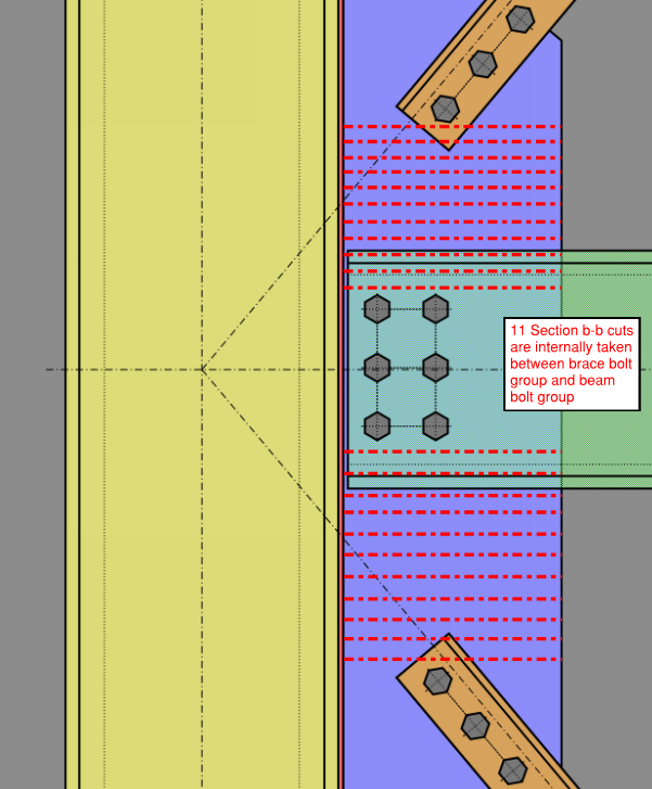
For each extended shear tab without gusset connection, the critical section is assumed to occur outside of the beam bolt groups and somewhere in between the beam bolt group and brace (upper or lower). 11 equidistance section cuts are taken between the extents of the beam bolt groups and braces (i.e. 22 section cuts in total for the case where there are top and bottom braces). The results are then only reported for the critical section, that is, the section producing the highest unity check.
See figure below delineating how the section cuts are taken internally.
Section b-b cuts
The uniform force at the column is at the face of the column flange as opposed to the column bolt line and gusset-to-beam interface
Beta will always be centered on the gusset plate. This means that the connection between the gusset plate and column will be centered on the gusset plate.
For the extended shear tab the length of the gusset failure plane is conservatively taken as the spacing between the bolts plus a 1.5” extension on both sides. In the instance that the bolt edge is less than 1.5”, the program will use that bolt edge distance instead.
This can be expressed as the following:

There is not clear direction as to how much of the shear tab should be used for this failure plane however the basis for the program assumption aligns with the assumptions used in the AISC seismic manual design examples.
Ex = Horizontal distance from ace of support to center of bolt group
Ey = Vertical distance from center of bolt group to center of beam
The determination of the K (effective length factor) is based on guidance provided AISC Design Guide 29 where K=0.5 is used if the gusset is supported on two sides and K=1.2 if it is supported on one side only. K = 0.65 is used when the gusset plate is used in a Chevron configuration.
For both the extended shear tabs (without and with gusset), the program will always assume the compressive concentrated load on the member is close to the column. This translates to the following conditions when determining the capacities for these limit states:
Column web yielding: Concentrated force is less than or equal to the depth of the member -> AISC 15th Ed Eqn J10-3
Column web crippling: Concentrated force is less than d/2 -> AISC 15th Ed Eqn J10-5
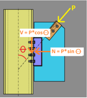
The Knee Brace configuration supports a single brace framing into either a beam or a column. The brace is assumed to only carry axial load which means that the gusset to beam/column connection is only designed for axial and shear forces. If the brace connection is eccentric, the moment due to eccentricity will also be reported, although not used for design.
Note:
See below for more information on Gusset Plate design and connection eccentricity.
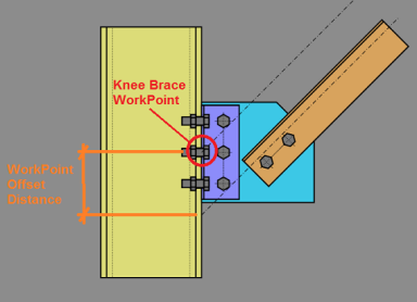
Because a Knee Brace frames into a beam or a column, not both, there is no beam to column intersecting work-point. Therefore, we consider the work-point to be the brace center-line intersection with the centroid of the gusset to beam (or column) connection.
The program uses simple statics to determine the force components at the gusset to beam/column connection.
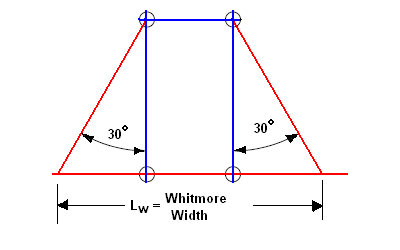
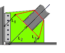
The Whitmore section is a design term used to indicate the portion of the gusset plate that is effective in resisting the tension or compression forces transferred to it by the vertical brace. As shown below (and in Figure 9-1 of the AISC 14th Edition Manual), the Whitmore section assumes that the gusset plate stress spreads out at a 30 degree angle from the first point of connection (along the line of the brace force). It then terminates at the last point of connection between the brace and gusset. This length is then defined as the width of the Whitmore Section.
The calculation of the Whitmore width is straight forward when the width remains entirely within the gusset. In cases, where the widths extends into the beam or column, RISAConnection assumes a constant thickness equal to the gusset plate thickness.
In cases where the geometry of the plate produces an eccentricity in the Whitmore section, RISAConnection will conservatively use a reduced effective width(see the article "The Whitmore Section" written by Thornton and Lini in the July 2011 issue of Modern Steel Construction.
The Whitmore section will be checked against both yield and rupture. With the width of the section as described above and the thickness of the section equal to the thickness of the gusset plate (or beam / column if a portion of the Whitmore section extends into the beam / column).
For compression, the gusset plate code check requires that Whitmore Section be viewed as an equivalent column. The width of the column is merely the width of the Whitmore section as discussed above. However, the compression checks also require an equivalent unbraced length KL for buckling checks. Currently the unbraced length used for the gusset compression checks is the unbraced length at the center of the Whitmore section (L2 as shown in the image below).
The K value used for the Gusset plate is assumed to be 0.50 for gussets that are supported along two edges and 1.2 for gussets supported along only one edge. K = 0.65 is used for a Chevron brace configuration.
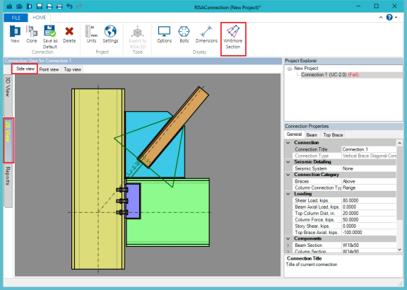
RISAConnection includes toggle buttons to view the Whitmore Section and unbraced length. These are available on the 2D Side View graphical view for vertical brace connections.
Note:
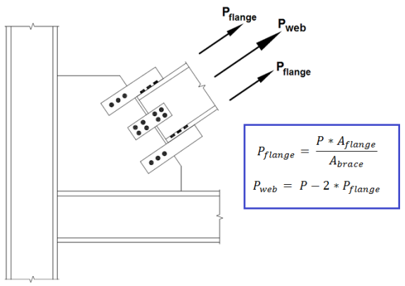
When a brace member is defined as a Wide Flange, it will connect to the gusset plate using claw (clip) angles. Because of the complexity of the brace to gusset connection, it is no longer appropriate to assume that the axial load is applied along the centerline of the brace. Instead, the load on the gusset plate is proportional to the cross sectional area of the connection element. This design methodology comes from Example II.C-2 from the AISC Design Examples Version 14.1.
When the brace is in compression, RISAConnection will conservatively calculate the Whitmore section and unbraced length based on the connection between the gusset and the claw angles.
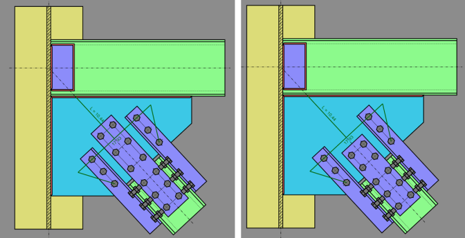
When the brace is in tension, RISAConnection will calculate the Overall Plate Tearout with the following assumptions:
Many of the diagonal brace connections result in a small connection eccentricity. This eccentricity may be minor for cases like the thickness of a plate (e.g. HSS brace with an end-tee or slotted plate connection), or it may be more significant (e.g WT brace with its flange bolted to the gusset plate). The design codes are not entirely clear on how to address this. Therefore, RISAConnection has used material outside the code specifications to arrive at the following design procedure:
When the eccentricity is the thickness of a single plate or gusset, then the program considers this eccentricity in the connection design using a procedure given in AISC Design Guide 24, Hollow Structural Section Connections. Section 5.2 of this design guide covers End Tee connections and gives formulas 5-1 and 5-2 to address the issue of interaction between the compression or tension in the tee stem and the flexure due to the connection eccentricity.
Single angle braces or WT braces where the flange of the WT is connected to the gusset plate will generally result in more significant eccentricities. While the code is silent on this subject, RISAConnection chooses to ignore this moment in the design of the connection itself. For more information on this assumption, see the article "Horizontal Bracing" by Dowswell, Brice, and Blain from the July 2010 issue of Modern Steel Construction. The idea is that the moment will be primarily resisted by the brace member instead of connection. The program will report the magnitude of this moment so that the engineer may manually include it in the design of the brace member itself.