Punching shear calculations are provided for columns/pedestals that land on concrete slabs. Here is some information on those calculations.
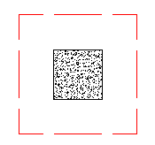
Punching shear is a phenomenon where a concentrated force on a slab causes a shear failure cone that "punches" through.
Punching shear calculations require a demand value and a capacity value. Many hand calculations will consider a punching shear force against a punching shear capacity force. This works if only shear force is present, but is insufficient if a moment is occurring on the column/pedestal. Thus, a stress demand/stress approach is taken. The applied shears and moments, along with the shape of the punching shear failure cone are used to calculate a maximum punching shear stress.
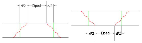
The effective depth of the slab is used to define the punching shear perimeter at a distance of d/2 beyond the edge of the column/pedestal.
The effective depth is based on the smallest depth to centroid of reinforcing for the Design Strips that encompass the pedestal. In cases where no design strips are defined at the pedestal location, the program will assume the bar size and cover specified in the first rule defined in the Design Rules spreadsheet.
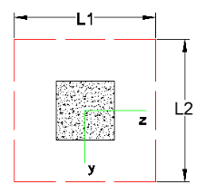
Length of the critical section along the local axes. This value is used to define the punching shear perimeter as well as to define how much of the moment is transferred by eccentricity of shear (as opposed to the portion transferred by flexure).
Note:
This is a property (Jc) of the critical section which is analogous to polar moment of inertia about the local
Note:
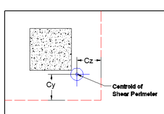
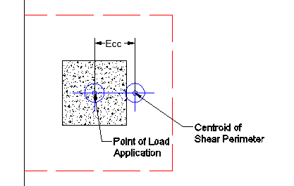
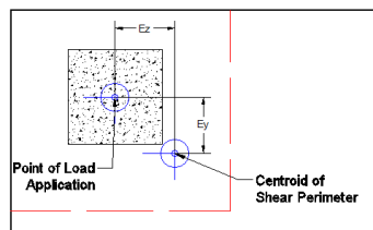
These give the distance from the shear perimeter edge to the centroid of the shear perimeter. For an interior punching shear perimeter this will always be L1/2 or L2/2. For edge and corner cases this value is calculated as the moment of area of the shear perimeter/area of the sides.
Note:
This is calculated from the dimensions of the assumed punching shear perimeter. It represents the fraction of the unbalanced moment for each axis that is transferred by eccentricity of shear.
Note:
The Total Stress is the direct shear stress plus the shear stress due to moment. This calculation uses the geometry of the punching shear failure cone along with the induced shear and moment forces to come up with a maximum stress. This will always occur at one of the failure cone corner locations. For an example calculation see the ACI 318-14 Section R8.4.4.2.3 (ACI 318-11 Section R11.11.7.2).
Note:
This represents the shear stress capacity of the slab calculated based on the three ACI equations for two way or punching shear capacity of the slab. Refer to ACI 318-14 Section 22.6 (ACI 318-11 Section 11.11.7.2) for more information. When ACI 318-19 is selected, the shear strength of concrete (Vc) uses equations in Table 22.6.5.2. Note that an additional size effect factor λs is added in the equation, λs is a function of effective depth of the slab d, and is calculated per Equation (22.5.5.1.3).
Note:
Minimum Slab Reinforcement at Punching Shear Critical Section
ACI 318-19 requires a minimum slab reinforcement at punching shear critical section if vuv>φ2λφ√f’c per Section 8.6.1.2. The As,min is calculated and presented in the punching shear result of
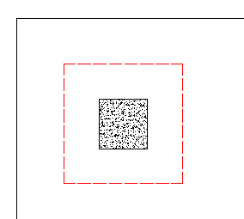
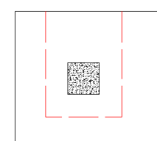
In RISAFloor ES there is the ability to add a shear cap, a thickened slab portion around the column to help with punching shear. A shear cap can be drawn at the same time as drawing a column:
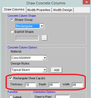
It can also be added graphically using the Modify Properties tab of the Draw Columns dialog, or it can be added via the Shear Caps tab of the Columns spreadsheet.
Note:
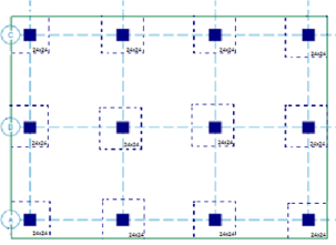
When a shear cap is applied to a column dashed lines will show up in the model view to indicate the shear caps.
When a shear cap is present at a column location the calculations are very similar. However, two checks are done, one for the slab depth punching shear and one for the shear cap depth punching shear.
Note:
![]()
The Shear Caps spreadsheet gives a tabular view of all shear caps defined on each slab floor in the model.
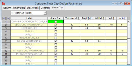
This is the column label at the specific lift.
This allows you to toggle on or off a shear cap at a specific column at a specific floor.
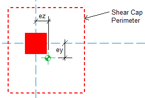
This is the thickness of the shear cap, which is the additional thickness beyond the regular slab thickness.
These are the plan dimensions of the shear cap and are based on the local axes orientation of the column. The depth is the dimension in the local y axis of the column and the width is the dimension in the local z axis.
These are the eccentricities of the shear cap from the column. A positive value indicates a positive eccentricity along the local axes of the column and vice versa for a negative eccentricity. See the eccentricity section for more information.
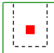
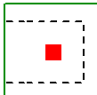
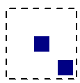
Punching shear loading includes a direct shear component, as well as biaxial moments. It is these combined forces that are used to determine the punching shear stress and code check.
The direct punching shear demand is not exactly just the axial force in the Column. The area within the punching shear perimeter loading is assumed to pass directly into the support, so that force must be discounted.
This includes
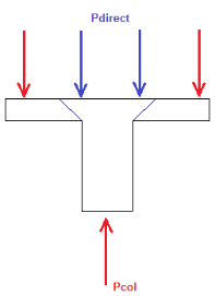
For the image above the Vu demand equals P
Note:
When there is a shear cap the program uses the exact same Vu for both the slab and shear cap punching shear checks. This is a conservative assumption. It is possible that a load will occur between the slab punching shear perimeter and the cap punching shear perimeter, but the program conservatively assumes this load goes into both punching shear calculations.
The moments used are also not necessarily just the moments directly from the Column. If the centroid of punching shear area is not the same as the centerline of the Column, then there will be an eccentricity that also adds/subtracts moment.
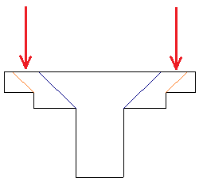
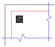
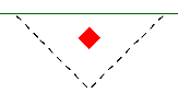
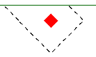
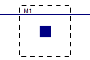
Take the edge punching shear situation shown below:
The punching shear perimeter is to the right of the center of Column location. This causes a moment in the punching shear calculation even if a moment is not explicitly applied on the Column. This eccentricity is automatically accounted for in the punching shear stress calculation.
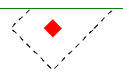
This same inherent eccentricity occurs in corner punching shear conditions. In this case, however, you get an induced moment in both local axes directions because of the centroid of shear perimeter location. This, similar to the edge condition, is automatically considered in the calculation of the maximum shear stress.
When using shear caps they can be drawn asymmetrically from the center of the column. If this is done then there will automatically be an eccentric moment created. This moment will automatically be accounted for when determining the maximum punching shear stress.
Note:
The program considers as many as nine different punching shear perimeters for each column in the model. different scenarios. We look at the interior, four edges, and four corner cases and determine which configuration produces the largest code check and present that in the results.
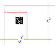
For example, let's consider a Column that has an interior punching shear perimeter close to a corner.
Here the program will also check out any EDGE punching shear perimeter considerations. The two below would be the most likely ones for this given geometry.
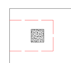
However, these other two edge conditions will also be checked:
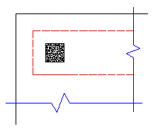
In most cases these odd situations will not govern. However, large moments in a given direction can cause punching shear perimeters with larger areas to govern in specific cases.
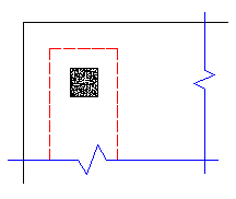
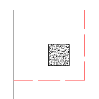
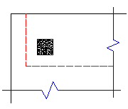
The program will also check out any CORNER punching shear considerations. The one below would be the most likely for this given geometry.
However, these other three corner conditions will also be checked:
In most cases these odd situations will not govern. However, large moments in a given direction can cause punching shear perimeters with larger areas to govern in specific cases.
Whichever configuration produces a maximum code check will be reported in the punching shear results.
Note:
When the program tests all different cases to determine whether a corner or edge situation governs, it bases the controlling case on the maximum code check produced. There are cases where an edge case is governing that by inspection you might think it would be a corner case. See the images below:
|
|
|
|
|
|
| Corner Case | Edge Case 1 | Edge Case 2 |
In these two punching shear scenarios shown above, by inspection you would likely expect the corner condition to control over the edge ones. Punching shear capacity is based on a minimum of three equations in the ACI code. One of these equations has an alpha term in it, where alpha is smallest for a corner condition. If this equation governs, this would guarantee the corner condition would have the smallest capacity. However, if this equation does not govern then these capacities may not be as different as you might expect.
Also, the demand portion of the equation will be different based on the geometry of the shear perimeter. It is possible that the edge cases produce a larger maximum stress than the corner cases.
In summary, our testing has shown that these non-intuitive scenarios where an edge controls over a corner have occurred in some instances.
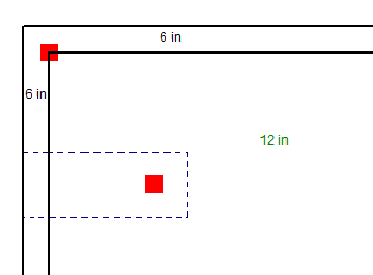
It is possible to have different slab thicknesses within a single column/pedestal's punching shear perimeter. If there is a different thickness at any point along the punching shear perimeter, the program will use the thinnest thickness for the entire calculation. When there is a different thickness, there will be a warning message in the Detail Report. The L1 and L2 values, for use in calculating the bo, will use the depth at the location of the pedestal/column.
A slab thickness can be changed using the thickened slab tool or drop panels. The slab can be thickened anywhere and in this case the edge of the slab is thinner than the center. Since the punching shear perimeter will be checked for all cases including edge cases, in this example the slab will be assumed to be 6" because it crosses both a 12" section and a 6" slab section. The thinnest thickness will be used and it may govern.
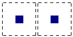
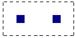
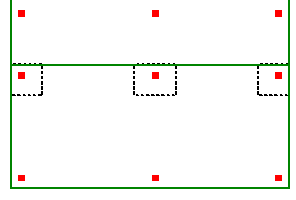
It may be possible for multiple, closely spaced Column to create a punching shear perimeter around the GROUP of piers at a lower force level than would be observed by investigating any one of the individual Column. This is NOT currently considered in the punching shear code checks.
|
|
| Individual Punching Shear Perimeter | Group Punching Shear Perimeter |
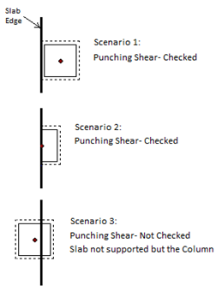
When a beam or wall panel is co-linear with the Column joint, the program will not provide a punching shear check on the Column. In these cases a code check of NC or "no calc" will be listed.
|
|
| Wall Co-Linear with a Column | Beam Co-Linear with a Column |
Note:
When a beam
If a beam, column or wall lands inside of or crosses a shear cap we will give code checks, but again the calculations will not be influenced by these elements.
|
|
|
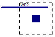
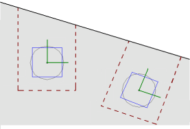
The punching shear perimeters are always investigated with respect to the Column local axes. As shown below, there may be cases where these local axes do not correspond to the slab edge or corner geometry adjacent to that Column. In cases like these it is possible for this to result in an artificially large assumed punching shear perimeter.
If either the slab edge is sloping or a column local axis is rotated it is possible to get edge shear perimeters as shown below:
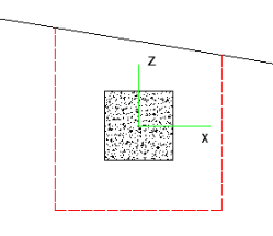
In these cases the program will calculate the Polar Moment of Inertia by summing up the three individual sides to get a total value.
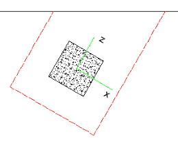
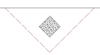
If either the slab edge is sloping or a column local axis is rotated it is possible to get a corner shear perimeter. The program will start by trying to draw the full shear perimeter. When this happens in this case we find that the shear perimeter has two parts of it that run into a slab edge. When this occurs the program considers this a corner. In this case
Note in the image below a case where when checking the punching shear on a shear cap the program may still have edge and corner conditions to consider. When the rectangular perimeter of the shear cap hits the slab edge it will be clipped back to the slab edge as shown.
In green you can see what the punching shear perimeter looks like for interior, edge and corner cases. Because the interior case falls off of the edge this case automatically gets discarded and a corner or edge failure must occur. However, in the case above both the corner and edge cases must punch through the shear cap AND a portion of the regular thickness slab.
The program calculates these shear perimeters appropriately but always uses a consistent depth that is the depth of the cap. Thus, the program simplifies this calculation.
Note:
When calculating the punching shear perimeter for a round Column, the program always converts the dimension into an equivalent square of equal perimeter. This greatly simplifies the calculation of punching perimeters when close to an edge or corner.
For an example of this let's use a 12" diameter. The perimeter = Pi*Diameter = 37.7 in.
An equivalent square would have a side dimension = 37.7 in/4 = 9.424"
Thus, a 12" diameter round Column would be considered a 9.424" x 9.424" square for use in punching shear checks.
The program will not consider an adjacent slab when performing a punching shear check. Only the slab that the column is drawn on will be consider and the slab edge will be considered free for punching shear checks.
The program currently does not allow for shear reinforcement. The only capacity considered for punching shear is the concrete itself. ACI 318-14 sections 22.6.6 (shear reinforcement), 22.6.9 (shearheads) and 22.6.8 (headed shear stud reinforcement) are not supported. ACI 318-11 sections 11.11.3 (shear reinforcement), 11.11.4 (shearheads) and 11.11.5 (headed shear stud reinforcement) are not supported.
It is possible that punching shear failures can occur around walls (especially walls with a short length). It is also possible that punching shear failures can occur around point loads or non-concrete columns bearing on the slab. RISAFloor ES does not currently check for punching shear for these situations.