 button on the Drawing Toolbar. Select Loads from the Spreadsheets Menu and then
choose the spreadsheet that you wish to modify or delete.
button on the Drawing Toolbar. Select Loads from the Spreadsheets Menu and then
choose the spreadsheet that you wish to modify or delete.Loads can be defined and applied to the model graphically or from within the spreadsheets. There are a number of different Load Types that may used when loading the model. For more information about the application of each Load Type (
As you define the loads in the model, you will notice that each Load Type (deck load, area load, line load, and point load) is broken down into several pre-defined Load Cases such as pre-composite dead load, post-composite dead load, non-reducible live load, reducible live load, and such. These 'Load Cases' are the building blocks upon which the more general Load Categories are based. Please note that these 'Load Cases' are automatically assigned to 'Load Categories'. You will then use these Load Categories to define the various Load Combinations that you wish to solve. See Loads - Load Combinations for more information.
You may view the loads on your model for each load category or load
combination. This is an excellent way to verify the loads applied
to the model.
The Self Weight of
The 'Self Weight' is applied as a uniform distributed load along each
beam
Note
As you apply your loads, you will notice that each load is broken down into several pre-defined Load Cases such as pre-composite dead load, post-composite dead load, non-reducible live load, and reducible live load. These loads are the building blocks of the loads applied to the structure upon which the more general Load Categories and Load Combinations will be based.
Point Loads, Line Loads, and Area Loads are applied using the following possible Load Cases:
| Load Case | Abbreviation | Description |
|---|---|---|
|
Self Weight |
SW |
Weight of Columns, Beams, Walls. Calculated based on Density defined in Materials spreadsheet. |
|
Pre-composite Dead Load |
PreDL |
Superimposed Dead Load existing prior to concrete deck hardening. |
|
Post-composite Dead Load |
PostDL |
Superimposed Dead Load existing after concrete deck hardening. |
|
Live Loads |
LL-Non |
Non-Reducible Live Load |
|
|
LL-Reduce |
Reducible Live Load |
|
|
LLS-Non |
Non-Reducible Live Load for garages, public assembly areas, live load magnitudes > 100psf |
|
|
LLS-Reduce |
Reducible Live Load for garages, public assembly areas, live load magnitudes > 100psf |
|
|
RLL-Non |
Non-Reducible Roof Live Load |
|
|
RLL-Reduce |
Reducible Roof Live Load |
|
|
SL |
Snow Load |
|
|
SLN |
Non-Shedding Snow Load |
|
|
RL |
Rain Load |
|
Other Loads |
OL1 |
Other Load 1 |
|
|
OL2 |
Other Load 2 |
|
|
OL3 |
Other Load 3 |
|
|
OL4 |
Other Load 4 |
|
Dynamic |
Dyn Mass |
Seismically Participating Load (for RISA-3D seismic weight calculations). This number should typically be greater than or equal to PostDL. |
|
Vibration Live Load |
VL |
Realistic Live Load (for floor vibration checks). Often much less than live load for strength design (LL). |
The 'Loads Cases' that are specific to decks or slabs are defined within the Deck Definitions Spreadsheet. These load cases are described in the table below:
| Load Case | Abbreviation | Description |
|---|---|---|
|
Deck / Slab |
Deck SW |
Deck or Slab Self Weight (auto-calculated based on Deck Material Type) |
| Construction Dead Load |
Const DL |
Comparable to PreDL, but a property of the deck instead of an applied load. |
|
Construction Live Load |
Const LL |
Live load present prior to concrete deck hardening. |
| Superimposed Dead Load | Super DL | Comparable to PostDL, but a property of the deck instead of an applied load. Often used to account for flooring materials, fireproofing. |
| Load Category | Includes Addition of Load Cases | Sloped Members Load Direction |
|---|---|---|
|
DLPre |
SW + Deck SW + Const DL + PreDL+ Super DL |
Y |
|
LLConst |
Const LL |
PY |
|
DLConst |
Const DL |
Y |
|
DL |
SW + Deck SW + PreDL + PostDL+ Super DL |
Y |
|
LL |
LL-Non + LL-Reduce |
PY |
|
LLS |
LLS-Non + LLS-Reduce |
PY |
|
RLL |
RLL-Non + RLL-Reduce |
PY |
|
SL |
SL |
PY |
|
SLN |
SLN |
PY |
|
RL |
RL |
PY |
|
OL1 |
OL1 |
Y,PY,y |
|
OL2 |
OL2 |
Y,PY,y |
|
OL3 |
OL3 |
Y,PY,y |
|
OL4 |
OL4 |
Y,PY,y |
Note:
Modifying point loads, line loads, and
Modifying area loads (non-tapered) can be done graphically. Click the Draw Area Loads tool from the Drawing Toolbar and select the Modify Area Loads tab.
Deleting loads may be done manually within the spreadsheets or graphically using the
Delete button on the Drawing Toolbar. Select Loads from the Spreadsheets Menu and then
choose the spreadsheet that you wish to modify or delete.
The load direction indicates how the distributed loads are applied to the sloped members.
| Y- |
Loads applied in the global Y-axis |
| PY- | Projected load in the global Y-axis |
| y- | Load applied in the local y-axis |
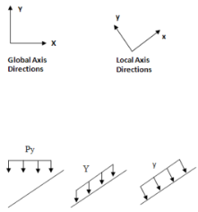
Positive loads are in the downward direction.
Keep in mind that global loads are applied without being modified for projection. For example, a full length Y direction load of 1 kip/foot applied to a 10 foot member inclined at 45 degrees generates a total force of 10 kips. Projected loads, on the other hand, are applied in the global directions but their actual magnitude is influenced by the member's orientation. The load is applied to the "projection" of the member perpendicular to the direction of the load. For example, a "PY" direction load is a projected load applied in the global Y direction. The actual magnitude of the load is the user entered magnitudes reduced by the ratio L/Projected length.
So the total load generated is equal to the input magnitudes applied along the projected length. This generated force is distributed along the full member length, so the applied magnitudes are reduced accordingly.