Dummy Members are used to simplify the framing in order to properly attribute load in complex regions. They must be weightless members and they must run parallel to the deck. Doing those two thing assures that these members will not receive any load of their own and will only serve to break a complex region into two smaller regions.
To Change a Beam into a Dummy Member:
Note:
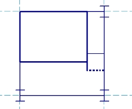
The image below shows two types of typical "stranded" columns. By calling it "stranded", we mean to point out that the framing around this column is incomplete. The load attribution code will tend to have problems with this type of situation. This sort of framing configuration will halt the solution. If properly detected by the program, it will result in a "framing error" which will identify the exact location of the framing issue. If not properly detected by the program, it could result in a more ambiguous error such as a Load Attribution or Polygon Error.
To correct this type of problem, you would typically add in a dummy member parallel to the deck that would frame out the column but would not receive any loading itself. An example of this type of correction is shown using the dashed lines in the image below. In order to avoid these types of framing problems a column must be connected on at least two sides:
The image below shows a typical "stranded" wall. By calling it "stranded", we mean to point out that the framing around this wall is incomplete. The load attribution code will tend to have problems with this type of situation. This sort of framing configuration will halt the solution. If properly detected by the program, it will result in a "framing error" which will identify the exact location of the framing issue. If not properly detected by the program, it could result in a more ambiguous error such as a Load Attribution or Polygon Error.
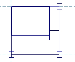
To correct this type of problem, you would typically add in a dummy member parallel to the deck that would frame out the wall, but would not receive any loading itself. An example of this type of correction is shown using the dashed lines in the image below. In order to avoid these types of framing problems a wall must have at least one beam (or wall) framing into each end joint of the wall.