Connections
The Connection Rules spreadsheets and settings are used for two purposes in RISAFloor:
- The analysis and design of columns with respect to the eccentricity effects caused by connections.
- The integration with RISAConnection for the design of hot-rolled steel connections.
Note:
- A RISAConnection license is not required for the analysis of connection eccentricity in the RISAFloor model.
RISAConnection can be used with RISAFloor and/or RISA-3D to design hot-rolled steel connections. The integration will send the member geometry, loads, and connection type information into RISAConnection. You can then open RISAConnection to edit/adjust the details of the connection. When satisfied with an appropriate connection design, you can then send the connection design results back into RISAFloor and RISA-3D for results presentation.
Available Connection Types
The list of available connection types depends on what version of RISAConnection you are integrating with. The list below represents the available connection options from the current version of RISAConnection:
- Beam to Column Shear Connections (shear tab, clip angle, end plate).
- Columns may be Wide Flanges, HSS tubes, or HSS pipes (shear tab only).
- Beams may be Wide Flanges or Channels (not for end plate).
- Double-sided connections available for clip angle shear connections into the column web.
- Beam to Girder Shear Connections (shear tab, clip angle, end plate).
- Girders may only be Wide Flanges.
- Beams may be Wide Flanges or Channels (not for end plate).
- Double-sided connections available for clip angle shear connections into the girder web.
- Shear Splices (beam and column).
- Columns may only be Wide Flanges.
- Beams may only be Wide Flanges.
- Beam to Column Flange Moment Connections (direct weld, extended end plate, flange plates, flush end plate).
- Direct Weld and Flange Plate moment connection columns may be Wide Flanges or HSS Rectangular Tubes.
- Extended End Plate and Flush Plate moment connection columns may only be Wide Flanges.
- Beams may only be Wide Flanges.
- Beam to Column Web Moment Connections (direct weld, flange plates).
- Columns may only be Wide Flanges.
- Beam may only be Wide Flanges.
- Beam to Column Web Moment Connections (Continuous beam over column).
- Columns may only be Wide Flanges, HSS Tubes, or HSS Pipes.
- Beam may only be Wide Flanges.
- Moment Splices (beam and column, direct weld, end plate, flange plate).
- Columns may only be Wide Flanges.
- Beams may only be Wide Flanges.
- Single Column Base Plate Connections
- Column may be a Wide Flange, Tube, or Pipe.
- Brace to Base Plate Connections
- Column may be a Wide Flange, Tube, or Pipe.
- Brace to Column Base Plate Connections
- Column may be a Wide Flange, Tube, or Pipe.
- Brace may be HSS Tube, HSS Pipe, Single Angle, Double Angle, WTs, or Channels.
See Troubleshooting below for more assistance with connection type limitations.
Integrated Connection Design Procedure
The steps required to design connections using this integration are as follows:
1. Completing the Full Structural Model
You must first draw your model in RISA-3D or RISAFloor. It is important that you use the Member Type (Column, Beam, VBrace, HBrace) designation properly. Otherwise your connections will not be designed. Keep in mind that connection design will only work for hot rolled connections at this point. Future versions will add to the current RISAConnection connection type capabilities.
2. Defining Connection Rules
Next, you must define Connection Rules. These rules allow you to define which types of connections you want to design in your model. You must have a rule for each type of connection you want considered. You may also want to create two separate rules for the same connection Type so you can manipulate these groups separately.
To open the Connection Rules spreadsheet click the  button on the Data Entry toolbar. Then create rules for each type of connection that you want to be designed with RISAConnection. The spreadsheet entries are explained below:
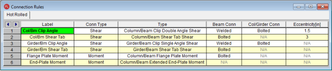
- Label - This is how you will identify your Connection Rule in other areas within the program. Each Connection Rule must have a unique Label.
- Conn Type - The Conn Type drop-down filters the list of Types into Shear, Moment, or Brace connections.
- Type - The Type refers to the different types of connections currently considered in RISAConnection. You will need to set up at least one connection rule for each connection type in your project. When you solve the connections in RISAConnection the member ends assigned to an individual Connection Rule will be grouped together.
- Note: You may have many double angle shear connections in your project. However, some are bolted with A325 bolts and some use A490 bolts. You should define these as separate Connection Rules.
- Beam Conn - This option defines how the beam is connected to the supporting pieces (plate, clip angle, etc). When you go to RISAConnection all connections grouped in this Connection Rule will default to this type of connection.
- Note:Many connections do not have options for these, so "N/A" will be shown
- Col/Girder Conn - This option defines how the supporting member (column or girder) is connected to the supporting pieces (plate, clip angle, etc.). When you go to RISAConnection all connections grouped in this Connection Rule will default to this type of connection.
- Note: Many connections do not have options for these, so "N/A" will be shown
- Eccentricity - This value has no effect on the RISAConnection integration. Instead it is used for analysis purposes. In models integrated with RISAFloor, beam/column shear connections add an automatic eccentricity equal to half the column's depth automatically (see the Model Settings-Solution tab for more information on this). However an additional eccentricity away from the column face may be entered in the Connection Rules spreadsheet. The value entered here should be equal to the distance between the face of column and the resultant beam end reaction (i.e. centroid of bolt/weld group on beam web).
- This column is only available in RISAFloor and in RISA-3D if you came in from RISAFloor.
- This eccentricity is only applied to beams which connect to columns and which have the Connection Rule specified in the Connections tab of the Beams spreadsheet.
3. Assigning Connection Rules
Once the Connection Rules are defined they must be applied to the member ends in your model.
- For Column/Beam connections the rule is assigned to the beam end but not the column.
- For Girder/Beam connections the rule is assigned to the beam end but not the girder.
- For Column/Beam/Brace connections the rule is assigned to the beam and brace(s) ends but not the column.
- For Chevron Brace connections the rule is assigned to the brace ends but not the beam.
- For Knee Brace connections the rule is assigned to the brace ends but not the supporting beam or column.
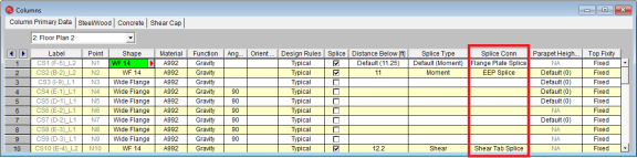
- Column Splice connections are applied as the Splice Connection Type in the Columns spreadsheet.
- Baseplate connections (as the Column Splice Connection Type) may only be applied at the bottom-most floor level.
Assigning the Connection Rules Graphically:
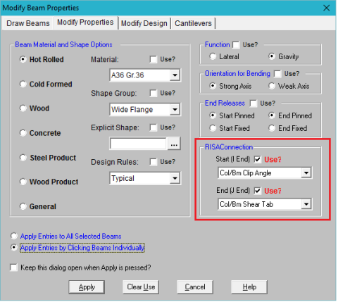
- To assign Connection Rules graphically click
 on
the Drawing toolbar and click on the Modify Properties tab.
on
the Drawing toolbar and click on the Modify Properties tab.
- Select the proper Connection Rule for both the Start and End of the member and check the Use check boxes. You can then either apply the entries to all selected members or by clicking members individually.
Assigning the Connection Rules in the Beams Spreadsheet:
The Connections tab of the Beams spreadsheet provides a place to assign, edit and view Connection Rules and column eccentricity settings as they apply to individual members.
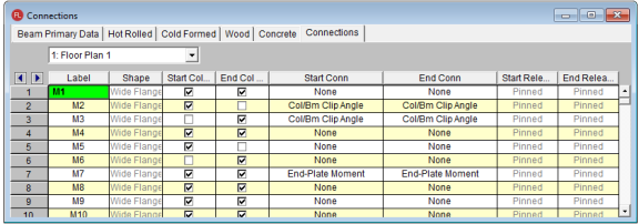
- Label - These are the member labels for all Hot Rolled Steel members in the floor.
- Shape - This allows you to view what shape is assigned to the member.
- Start/End Col Ecc - This allows you to specify whether the eccentricity between the column center-line and the beam's end reaction resultant should contribute additional moment to the design of the column. This option is only available for pinned beam ends which frame into columns.
- Start Conn/End Conn - These entries allow you to select a rule from the Connection Rules spreadsheet. You will need to know which end of the member is the Start (I end) and the End (J end), which you can view graphically.
- Start Release/End Release - The end release for the beam is reported here. This is useful in verifying the that the chosen connection for the beam is valid for its end fixity (i.e. shear connections for pinned-end beams).
Note:
- Connections can only be designed for Hot Rolled Steel members, so only those members are shown on this tab in the spreadsheet.
- Column splices can be applied in the Columns spreadsheet. The splice fixity (shear vs. moment) will be determined based on the column Splice Type.
- Only base plate "splices" may be applied at the lowest level columns.
4. Assigning Load Combinations
Once you have all of your Connection Rules assigned properly you must define which load combinations that you wish to use for connection design.
On the Design tab of the Load Combinations spreadsheet there is a check box for Connection. This check box defines whether you want your connections designed for that LC or not.
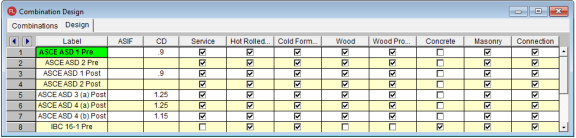
There are times where the member design may be designed by LRFD methods and the connections designed by ASD methods. This check box allows for that flexibility.
5. Designing Connections
To design connections you must first have either a Single LC or Batch solution present. Once there is a solution, there are two ways to design connections.
- Choose Solve - Design Connections.
This option will not automatically open RISAConnection. Instead, it will run in the background, using whatever default or previous settings are in RISAConnection. Once you've done this the Connection Results browser will be populated. To fully export into RISAConnection, use the Director tool, as shown next.
- Choose Director - RISAConnection.
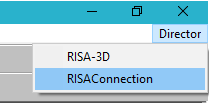
This option will automatically launch RISAConnection where you can modify the connection parameters, such as number of bolts, clip angle size, clearances, etc., for all the valid connections in your project (see the RISAConnection Help file for more information on how to design connections using RISAConnection). You can then solve your model in RISAConnection and then send the information back to RISAFloor to populate the Connection Results browser.
RISAConnection File Creation and Workflow
When using RISAConnection integration, a RISAConnection file will be created automatically. The file will have the same naming convention as the RISAFloor file and will be created in the same directory as the RISAFloor file. It will have a .rcn file extension.
Once this RISAConnection file is created then you can use this file separately to make connection changes. The file can be transferred to another machine and worked on separately. Items related to the connections can be modified (bolt criteria, weld criteria, connector sizes, clearances, edge distances, etc.). You can then modify/design your connections so that they now work. Then, simply move that file back to the location where the RISAFloor model is located and then redesign connections in RISAFloor. These changes will then be considered.
Note that any items defined by the RISAFloor models can not be modified (beam/column sizes, bolted vs welded connections, design code, etc). Any of these changes must be taken care of in RISAFloor and then sent back over to RISAConnection.
6. Connection Design Results
Once the connections have been designed in RISAConnection from either of the methods above the results will be available in RISAFloor. You can view the results browser or see color-coded results graphically.
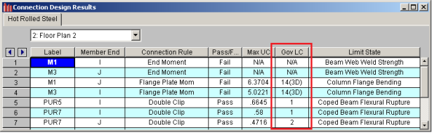
Connection Results Browser
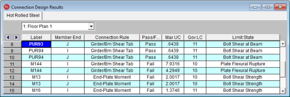
- Label/Member End - These fields give the location in the model that this connection result corresponds to.
- Connection Rule - Shows the Connection Rule assigned to this location.
- Pass/Fail - Tells whether the connection passes ALL connection checks or not.
- Max UC - Gives the maximum unity check for the worst case LC.
- Gov LC - Gives which LC provided the Max UC.
- Limit State - Gives the governing Limit State which produced the worst case code check or failing criteria.
When viewing this browser there is a button at the top of the screen, Detail Results for Current Connection.

Clicking this button will open up RISAConnection to this specific connection, allowing you to take a further look at the connection results and allow you to edit connection properties in a quick, efficient manner.
Note
- The Limit State field will also give notes for any connections that were not able to be designed in RISAConnection. See the Troubleshooting section below.
Viewing Results Graphically
Click on the Member End Display button from the Windows toolbar to view the connection results directly on your model, in color-coded view. The labeling will display the governing unity check value.
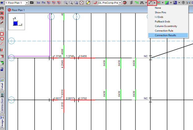
If you are in a graphic view and have valid connection results you can also press the Connection button on the left-hand side of the screen.

This will give a Connection cursor  and allow you to click on a member end that has a Connection Rule defined and will open RISAConnection to the specific connection that you clicked on.
7. Multiple Round Trips Between RISAFloor/RISA-3D and RISAConnection
When round tripping between RISAConnection and RISAFloor/RISA-3D multiple times there are a few items to consider:
- After the first pass into RISAConnection, connection property changes in the RISAConnection file will be saved. This means that if the RISAFloor/RISA-3D model is modified and the connections are re-designed you will not lose the connection information that you have modified.
- One exception to this is if you make a change to the Connection Rule for that member end. If that occurs then the basic input of the connection is modified and your connection changes will be deleted and replaced with the new connection's default settings.
- Thus, you are able to work on a RISAConnection file separately from the RISAFloor/RISA-3D file. You can then re-locate them back in the same directory and they will be able to work together, as long as none of the Connection Rules changed in RISAFloor/RISA-3D. Any change of an individual member end's Connection Rule will wipe out any changes made in the RISAConnection file.
Troubleshooting RISAConnection Integration
If you have difficulty getting your RISA-3D or RISAFloor model to integrate into RISAConnection, it is possible that you have defined connection or member information incorrectly, or there may be a program limitation which prevents the integration. Please see below for assumptions, modeling rules, and possible error messages.
Moment Connection Considerations
The following moment connections are currently supported in RISAConnection:
- Beam to column flange plate moment connections for wide flange or HSS tube columns and wide flange beams.
- Beam to column direct weld end plate moment connections for wide flange or HSS tube columns and wide flange beams.
- Beam to column extended end plate moment connections for wide flange members.
- Beam to column partially extended end plate moment connections for wide flange members.
- Beam to column flush end plate moment connections for wide flange members.
- Column flange plate moment splice.
- Beam flange plate moment splice.
- Column direct weld moment splice.
- Beam direct weld moment splice.
- Column extended end plate moment splice.
- Beam extended end plate moment splice.
Continuous Beam over Column Connections
In order to properly export a continuous beam over column connection to RISAConnection you must obey the following rules:
- A Continuous beam over column connection rule must exist in the Connection Rules spreadsheet.
- That connection rule must be applied at the top of the column where a continuous beam passes over it.
- No other column members from above can frame into the connection.
- Connection rule must be applied to the top most floor of the structure.
- The column member must be a prismatic Wide Flange, a HSS Tube, or a HSS Pipe.
- The beam member must be a prismatic Wide Flange.
Shear Connection Considerations
The following shear connections are currently supported in RISAConnection:
- Single or double clip-angle connections for wide flanges
- Shear tab connections for wide flanges
- End plate connections for wide flanges
- Single or double clip-angle connections for channel beams
- Shear tab connections for channel beams
- Double-sided double clip angle connections to the column or girder web.
- Beams on either side of the web must be within 3 inches (parallel) to be considered a double-sided connection.
Vertical Brace Connections
The following vertical brace connections are currently supported in RISAConnection:
Diagonal Brace Connections
In order to properly export a diagonal brace connection to RISAConnection you must obey the following rules:
- A Diagonal Brace connection rule must exist in the Connection Rules spreadsheet.
- That connection rule must be applied to the end of the VBrace which connects to the gusset
- That connection rule must also be applied to the end of the beam which connects to the gusset and to the column.
- There may be one or two VBrace members per connection. If there are two VBrace members, they must frame in from above and below the beam respectively
- There must be one beam member on the same side as the VBrace per connection.
- The VBrace(s) may be offset from the beam / column work point. If the offset is along the length of the column then each brace cannot be more than 18 inches from the work point. If the offset is along the length of the beam then the two VBrace members must share a common work point. This eccentricity will be accounted for in the design of the connection. But, the connection design will NOT consider any of the EBF (Eccentrically Braced Frame) requirements of AISC seismic provisions.
- The beam must be horizontal, and the VBrace cannot have an angle of less than 10 degrees with respect to the Beam or the column.
- The column must be a prismatic Wide Flange, a HSS Tube, or a HSS Pipe.
- The beam must be a prismatic Wide Flange.
- The brace(s) must be a single angle, double angle, channel, tube, pipe, WT, or prismatic Wide Flange shape.
Chevron Brace connections
In order to properly export a Chevron Brace connection to RISAConnection you must obey the rules below:
- A Chevron Brace connection rule must exist in the Connection Rules spreadsheet.
- That connection rule must be applied to the ends of both VBraces which connect to the gusset.
- There must be exactly two VBrace members per connection. They must frame in from the same side (above or below) of the beam.
- The VBraces need not share a common node. However, any eccentricity that exists will not be accounted for in the connection design.
- The beam and VBraces must exist in the same plane.
- The beam must be horizontal, and the VBraces cannot have an angle of less than 10 degree with respect to the beams or the vertical plane.
- The beam must be a prismatic Wide Flange, a HSS Tube, or a HSS Pipe.
- Note: Currently HSS beams on seismic chevron braces are not supported.
- The brace(s) must be a single angle, double angle, channel, tube, pipe, or WT, or prismatic Wide Flange shape.
Knee Brace Connections
In order to properly export a Knee (or Kicker) brace connection to RISAConnection you must obey the following rules:
- A Knee Brace connection rule must exist in the Connection Rules spreadsheet.
- That connection rule must be applied to the end of the VBrace which connects to the gusset. This can either be at the end that connects to a beam or the end that connects to a column.
- The VBrace cannot have an angle of less than 10 degrees with respect to the Beam or the column.
- The supporting member (beam or column) must be a prismatic Wide Flange, a HSS Tube, or a HSS Pipe.
- The Vbrace must be a HSS Tube, HSS Pipe, Channel, WT, Double Angle, or Single Angle shape.
- The Vbrace and its supporting member (beam or column) must be in the same plane.
Splice Connections
RISAConnection can design wide flange splice connections for beam and column splices. These can be either shear or moment splices. Keep in mind these items when creating your model:
- For beam to beam column to column splices, both members must be oriented in the same direction.
Base Plate Connections
RISAConnection can design single column base plate connections for shear and/or moment forces. Keep in mind these items when creating your model:
- A Base plate connection rule must exist in the Connection Rules spreadsheet.
- The column must be a Wide Flange, a HSS Tube, or a HSS Pipe.
- Base plate connection rules may only be assigned to the bottom of a column member.
Brace to Base Plate Connections
RISAConnection can design vertical brace into a column base plate connections for shear and/or moment forces. Keep in mind these items when creating your model:
- A Brace to Base Plate connection rule must exist in the Connection Rules spreadsheet.
- The column must be a Wide Flange, a HSS Tube, or a HSS Pipe.
- The brace must be a HSS Tube, HSS Pipe, Channel, WT, Double Angle, or Single Angle.
- Base plate connection rules must be assigned to the bottom of a column member and the end of the brace that connects to the column.
- The brace end node may be offset along the column center-line up to 24 inches away from the end of the column.
Truss HSS T-Connections
RISAConnection can design HSS T-Connections that have been exported from your RISA-3D model. Keep in mind these items when assigning the connection rule in RISA-3D:
- A Truss HSS T-Connection rule must exist in the Connection Rules spreadsheet.
- The branch member (vertical member) must be an HSS Tube section.
- The chord member (horizontal member) must be an HSS Tube section.
- The branch and chord members may be assigned as one of the following Shape Type Combinations:
- Beam supported by Column
- Column supported by Beam
- VBrace supported by Column
- VBrace Supported by Beam
- HBrace supported by Column
- HBrace supported by Beam
- The chord member must be continuous under the branch. If the chord member is broken into two members it will not export.
- The branch and chord member must be in the same plane.
- The branch and chord member must be perpendicular to one another.
Integration Error Messages
If you try to send a connection to RISAConnection from RISAFloor or RISA-3D, the program will test whether that is a valid connection. If the program finds the connection or the Connection Rules to be incorrect or unsupported, then the program will not design the connection and will give the error in the Connection Results spreadsheet - Limit State column.
The possible error messages are:
- Connection not supported : This message will occur when there is a connection configuration that RISAConnection can not design. An example would be a horizontal brace connection where brace members frame into a beam web.
- Invalid or missing supporting connection members: This message will occur if the member(s) that a member is framing into is not of the proper material, shape, member type, etc. Also check that the Member Function is the same (lateral or gravity) for all members for a particular connection.
- Invalid connection member material: This message will occur if the member's material is not hot-rolled steel.
- Invalid connection member shape: This message will occur if the member's shape is not one of the supported shape types for that connection type.
- Invalid member/beam slope (more than 15 degrees): This message will occur if the member being connected has an invalid slope. Currently, beam/column connection design is only for orthogonal connections. If the angle between members is greater than 15 degrees from orthogonal then this message is given.
- Invalid member/brace rotation (more than 15 degrees): This message will occur if the member being connected has an invalid rotation. Currently, members can only be designed at certain orientations. For example, weak axis beam to column design is not currently supported and will instead give this message.
- Invalid member skew (more than 15 degrees): This message will occur if the member being connected has an invalid skew. Currently, beam/column connection design is only for orthogonal connections. If the angle skew between members is greater than 15 degrees from orthogonal then this message is given.
- Connections on skewed members are not supported: This is a similar message to the invalid member skew message.
- Invalid vertical brace connection: This message will occur if there was not a valid configuration. If there is not a valid column, beam and vertical brace intersection (at proper orientation, member type, member material, etc) then you may see this message. Note that for integration you must assign BOTH the beam and the brace to the vertical brace Connection Rule.
- Brace angle is invalid: For a corner brace or chevron vertical brace connection the brace angle with the column and beam must be > 10 degrees.
- Members have different/missing connection rules: If there is a vertical brace connection and the beam and brace have different Connection Rules, you will get this message.
- Beam must be a WF in a Chevron brace connection: This message will come up if you have assigned a chevron brace connection type to a tapered WF beam member.
- Beam and Column must be WF in Diagonal brace connections: This message will come up if you have assigned a diagonal brace connection type to a tapered WF beam member.
- Invalid connection. Connection is applied to a gravity member: This message will occur if a seismic connection rule is applied to a gravity member. These type of members require lateral solution results from RISA-3D, so it does not make sense to apply the connection to a gravity only member.
- Invalid code. HR Steel and Connection design codes must be the same: This message will occur if the design codes do not match on the Model Settings Codes tab. Seismic design requires that these match.
- Invalid design method. IMF/SMF connections must be design with LRFD: This message will occur if an IMF or SMF seismic connection is applied to a model that is assigned the AISC 360-10 (14th edition) ASD design code. Section 1.3 of the AISC 358-10 design code requires that seismic connection design must be done per LRFD.
-
Incomplete definition of connection rule: This message will occur if you have not selected an appropriate "Beam Conn" or "Col/Girder Conn" input in the Connection Rules spreadsheet. To correct this, simply go back to Connection Rules and select the connection type (Bolted or Welded).
-
Beam must be drawn continuously over the column: This message occurs when utilizing a Continuous Beam over Column connection type, and the beam framing is set to terminate at the column without spanning the entire width of the column. This error serves as a reminder to ensure that the beam is consistently drawn in a continuous manner over the entire top surface of the column.
Connection Types Not Currently Supported
- Skewed or sloped connections. If the skew or slope is less than 15 degrees, we will transfer the connection to RISAConnection as an orthogonal connection. If the skew or slope is greater than 15 degrees than the connection will not be transferred.
- Horizontal brace connections.
RISAFloor and RISA-3D Connection Design Interaction
RISAFloor and RISA-3D both have the ability to have their connections designed with RISAConnection. Thus, there are three possible scenarios for connections between RISAFloor, RISA-3D and RISAConnection:
- Connections that are only in RISAFloor (Gravity connections in a combined RISAFloor/RISA-3D model).
- Connections that are in both RISAFloor and RISA-3D (Lateral connections in a combined RISAFloor/RISA-3D model).
- Connections that are only in RISA-3D.
The third option above does not involve RISAFloor, thus it will not be discussed here.
RISAFloor Gravity Member Connections (Scenario 1)
Connections that are gravity in RISAFloor (option 1) are only RISAFloor members, which makes this more straightforward. When designing connections from RISAFloor you get a very similar behavior to what is shown in the behavior above.
The difference is when you use the Director to go into RISA-3D and then into RISAConnection, the Gravity connections are still in the RISAConnection project. The .rcn file contains BOTH RISAFloor AND RISA-3D connections. Therefore, when entering RISAConnection from RISA-3D, you will see more connections in RISAConnection then just those sent over from RISA-3D.
RISAFloor Lateral Member Connections (Scenario 2)
Additional items to consider are:
Load Combinations
Lateral connections in RISAFloor will also come into RISA-3D. Thus, two sets of load combinations will come into RISAConnection. Below is the Load Combination drop-down list from RISAConnection after coming in from a RISAFloor/RISA-3D model.
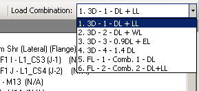
Here we can see that the RISA-3D LC's come in first followed by those from RISAFloor.
Note:
- This also occurs in scenario 1 above, except that all of the RISA-3D load combinations will have zero loading.
When reporting results in the Connection Results spreadsheets, both programs may list load combinations from the other program if those LC's happened to be governing. In RISAFloor it would look similar to the image below:
Naming Convention
RISAFloor and RISA-3D have different naming conventions for members. Thus, members taken from RISAFloor to RISA-3D will NOT have the same name between both programs.
RISAConnection will ALWAYS use the RISAFloor naming convention. This may be a little confusing. One way we have made this easier to comprehend is that in the Connection Results spreadsheet in RISA-3D we give BOTH the RISAFloor and RISA-3D label.
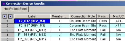
In this image the F1_B labels are the RISA-3D labels. The labels in parentheses are the RISAFloor labels.