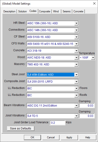
Steel Product design can be performed on standard steel joists. The steel products are automatically optimized based on minimum weight and based on the criteria specified in the Design Rules spreadsheet. There are options for Steel Joist Databases which have different capacity values. The Steel Joist Institute (SJI) Edition from which the values are determined are selected based on the Code specified in the Model Settings.
The following editions are supported:
SJI 45th Edition: ASD
SJI 43rd/44th Edition: ASD
SJI 42nd Edition: ASD
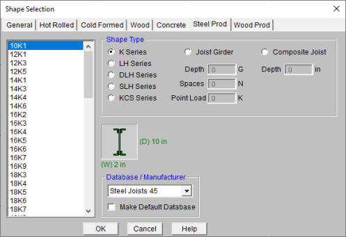
How To Apply a Steel Product Design Code
The various Steel Product databases may be accessed from the Beams
spreadsheet by clicking in the Shape field and then clicking
![]() .
.
Allowable loads for Steel Joists are based on the standard load and span tables for K, LH, DLH, and SLH Steel Joists. This also includes the short span K2.5 series Joists. These tables list a maximum allowable uniform load and a uniform load that will produces a deflection of L/360. The maximum allowable load (black number) is used directly by the program and cannot be adjusted. The L/360 load (red number), on the other hand, is used to obtain the joist stiffness for the given span. This load can be exceeded if a more relaxed deflection criteria (such as L/240) is specified in the Design Rules.
Steel products are designed to resist a uniform dead load (UDL), a uniform live load (ULL) and a uniform total load (UTL). The uniform dead load (UDL) on the beam includes the sum of the beam self weight, the deck self weight, and any applied / superimposed dead load.
The uniform live load (ULL) on the beam includes the sum of ALL the floor live load cases including the reducible and non-reducible versions of LL (Live Load), and LLS (Live Load - Special)as well as the controlling roof load (RLL, SL +SLN, or RL). Each of the roof loads are treated separately and are NOT added together for the calculation of the ULL or UTL. The uniform total load is the sum of UDL and ULL.
Per the SJI 100 - 2015, the design length shall equal the span minus 4 inches.
Note:
When considering non-uniform or concentrated loads, the joists must be designed for these special loading conditions. This may be done by specifying a KCS joist. If a KCS joist is not assigned by the user then a standard joist will be chosen from the design list, but will have an (SP) extension to indicate that the joist must be designed to resist the special applied loads.
KCS joists are joists that are designed to have a constant shear and moment capacity along the entire length of the joist. In RISAFloor, KCS joists are checked versus the constant moment capacity given in the KCS joist tables. They also check that the largest applied point loads is less than the shear capacity and that the algebraic sum of the distributed loads at a locations are less than the 550 plf maximum for K series joists. In these last 2 cases, the code check for a KCS joist may be the largest applied point load / shear capacity or the largest distributed load magnitude / 550. No special message is generated if either of these 2 checks are violated as the code check will come back > 1.0. KCS joists are also checked against the deflection requirements. Currently, KCS joists never get the “SP” suffix added.
When a joist has special loading that requires extra consideration, the most economical solution may be to use a standard joist that is capable of resisting the non-standard or special loading. When this type of design is given, the program will add an (SP) extension to that joist designation to indicate that it is resisting a non-standard load. Because this loading falls outside the normal design criteria for the joist tables, these (SP) joists may warrant further detailing by the engineer or joist manufacturer to insure adequate performance. The RISAFloor detail report provides a Special Joist Load Diagram which shows the Point Loads, Distributed Dead, and Distributed Live loads with their magnitudes and dimensions.
RISAFloor will choose a joist such that the capacity shear envelope of the joist under a standard uniform load is still greater than the actual shear at all locations along the length of the joist. Because the joist will have a shear strength greater than zero at the midspan of the beam, the shear envelope for a joist with a maximum uniform load capacity of W, would be given by the figure shown below:
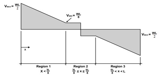
In addition to checking the shear envelope, the program will make sure that the maximum allowable moment is not exceeded at one point along the length of the joist. The maximum moment is defined as wL2/8, where w is the maximum allowable uniform load for that joist and span that is listed in the joist tables.
More information on this procedure can be found in the book, Designing with Vulcraft: Steel Joists, Joist Girders and Steel Deck, published by Nucor Corporation.
The program will perform Joist Girder design according to the basic Joist Girder tables given in the Steel Joist Institute tables and / or the Vulcraft catalog. The intended use is that the user will designate the depth of the Joist Girder before the model is solved. If a generic "Joist Girder " is chosen, then the program will optimize the beam by finding the Girder with the least DEPTH. This will often be a heavier member than is necessary for design. For this reason it is strongly suggested that the user provide a Girder depth whenever they specify a joist Girder.
RISAFloor will call out a Joist Girder in the design results using the following terminology:
16G4N2.4
Where:
The Joist Girder will be flagged with an (SP) if non-standard loading is detected. This includes situations where the magnitude or spacing of the concentrated loads vary by more than the Joist Girder Load Tolerance set on the Codes Tab of the Model Settings Dialog. Whenever the loading falls outside the normal design criteria for the joist tables, these (SP) joists may warrant further detailing by the engineer or joist manufacturer to insure adequate performance. RISAFloor provides a loading diagram in the detail report that can be directly supplied to the manufacturer for the design of the Joist Girder.
Note:
When only the depth of the girder has been specified by the user then the moment of inertia is approximated as:
Izz = .027*2.*4*(bm_len/12.)*JG_depth
When the user gives the number and magnitude of the point loads and the magnitude then the moment of inertia is approximated as:
Izz = .027*joist_spaces*point_load*(bm_len/12.)*JG_depth
Note:
The program will perform the Composite Joist (CJ) design according to the design approaches provided by SJI. The detailed design steps and assumptions are discussed in this section below.
The intended use is that the user will designate the depth of the Composite Joist before the model is solved. If a generic “Composite Joist” is chosen, then the program will optimize the beam by using the rule of thumb of L/18 provided by SJI for the design. L is taken as the span of the joist. For user input Composite Joist Depth, it needs to fall in the range of L/12 and L/30 as required by SJI. Currently it is prohibited to input joist depth that is out of this range in the program.
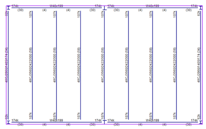
RISAFloor will call out a Joist Girder in the design results using the following terminology:
48CJ3540/2423/300 (58)
Where:
If there is non-standard loading on the joist, the program will calculate the maximum moment on the joist and convert that to an equivalent uniform load for the joist callout.
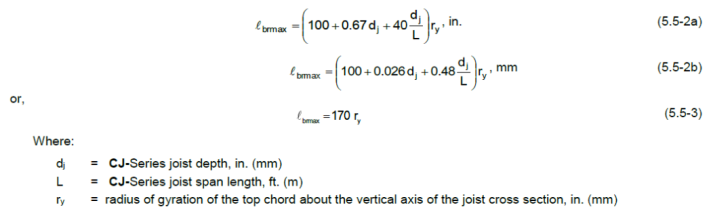
The number of bridging lines is calculated as: n = L/Lbrmax - 1.
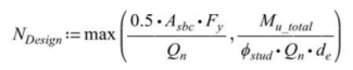
The number of required shear connections in half-span by design is calculated as.
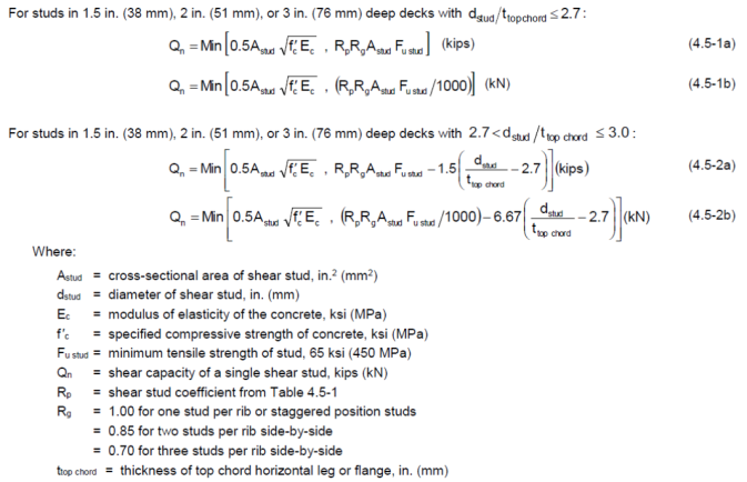
The shear capacity Qn for each stud is calculated based on the Composite Joist Specification (SJI 200-2015, Section 4.5.4). The equations are listed below:
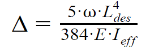
The post-composite deflection is calculated based on the effective composite moment of inertia Ieff per the following equation:
Note:
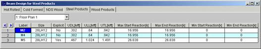
The results for the Steel and Wood Products tab are explained below. The steel product results give the uniform loads applied to the joists. The results for the wood products give the maximum bending moments and shears as well as the allowable moments and shears for the joist. The pull down list at the top of the spreadsheet allows you to toggle between floors.
The Label column lists the beam label.
The Size column displays the designation of the steel or wood product. When no adequate member could be found from the redesign list, this field will display the text “not designed”. Consider reframing, relaxing the design or deflection requirements (see Design Optimization), or adding more shapes to the available Redesign List (see Appendix A – Redesign Lists).
The Explicit column displays “Yes” if the beam has been locked to an explicit beam size by the user. When you have chosen a specific shape to override the programs automatic redesign, that beam becomes “locked” and will not be automatically redesigned by the program.
Note:
The UDL column for Steel Products displays the total uniform dead load on the beam. This includes the sum of the beam self weight, the deck self weight, and the applied dead load.
The ULL column for Steel Products displays the total uniform live load on the beam as described above in the Steel Products Design section. .
The UTL column for Steel Products represents the total of Dead plus Live loads and displays the sum of UDL and ULL.
Note:
The Max Start & End Reactions column displays the maximum start and end reactions of the beam for ALL load combinations. If “Show Factored End Reactions” in Model Settings is left unchecked, these displayed loads are not factored. If it is checked, then the displayed loads will have been multiplied by the factors in the load combinations. The sign convention assigns positive reactions to downward forces. Negative reactions, if they occur, would indicate uplift.
The Min Start & End Reactions column displays the minimum start and end reaction of the beam.
The program does not currently allow for a cantilevered extension of the top chord of a joist. If this is done, the program will NOT design the joist.
The program does not design continuous or fixed end Joists or Joist Girders.
No attempt is made to design joists for uplift forces or to call out bridging requirements that may be required during construction.
No attempt is made to calculate or design for the axial force imparted onto the members of the structure that will serve as the main chords of roof or floor diaphragms.
The program does not design joists for less than 10 feet because the allowable capacity joist tables do not give explicit capacities for shorter span joists.
Pre-composite design, camber design, long-term deflection, shear check are not provided in the program. These design checks need to be provided by SJI certified joist manufacturers. Vibration analysis for composite joists is also not provided currently.
Only 0.5 in, 0.625 in, 0.75 in stud sizes and 65 ksi stud Fu are currently supported for composite joist design.