Footing - Results
Upon completion of the analysis and footing design the results are presented in Results Spreadsheets, with a Detail Report for each footing. The Detail Report can be customized and printed. You can control what information is included in the Detail Report by clicking the Report Options button at the top of the Detail Report. Available report sections are listed for you to check those that you wish to include.
Solution Methodology
It is important to note that if the location of the load resultant is not within the footprint of the footing, then the footing is unstable. In this instance, the user is warned of the instability, which must be corrected by increasing the footing size or overturning resisting force.
The method RISAFoundation utilizes to obtain the soil pressure distribution provides an exact solution. RISAFoundation assumes the footing behaves as a rigid body and satisfies equilibrium equations. The contribution of the soil is determined through direct integration.
The calculation of the soil bearing profile for a two-way (biaxial) load state is the most complex calculation RISAFoundation makes. The soil is considered to resist compression only. If uplift is present, RISAFoundation allows that part of the soil to “let go”, so no soil tension is ever part of the soil bearing solution.
Soil bearing controls the plan dimensions of the footing; i.e. the footing is sized such that the actual maximum soil bearing pressure does not exceed the user-defined allowable soil bearing. The calculations use the service load combinations only. When an allowable bearing increase factor (ABIF) is specified, the allowable soil bearing is scaled up by the ABIF, typically a 1/3 increase. For more information, see Loads - Load Combinations.
Once the soil stress distribution has been solved, the load on the footing is known at every point. Direct integration on the contributing portion of the soil stress provides the shears and moments at the lines of interest.
Sketch and Details
RISAFoundation will optimize the dimensions of the footing for optimum concrete volume. The final footing geometry is presented in tabular form within the Footing Results Spreadsheet and graphically in the Footing Detail Report. The orientation of the footing is based on the footing's local x- and z-axes, respectively.

Click on the image to enlarge it
Footing Sketch
The Detail Report presents a sketch of the footing with dimensions (using the A,B,C,D reference system discussed in the Geometry section).
Footing Details
Footing details, shown below, may be included in the report. The details may also be exported to a DXF CAD file using the Export option on the File menu.

Soil Bearing Results
RISAFoundation displays the Soil Bearing check in a spreadsheet format on the Code Checks tab of the Footing Results Spreadsheet. The RISAFoundation Detail Report presents the soil bearing results for all service combinations. A soil bearing contour plot for each combination can also be displayed.

Click on the image to enlarge it
RISAFoundation displays color contoured images of the soil bearing profile, along with the bearing pressure magnitudes at each footing corner (QA through QD). Also provided is the location of the neutral axis (the line between compressive stress and no stress due to uplift). The location is given by NAX and NAZ values. These are the distances from the maximum stress corner to the neutral axis in the X and Z directions, respectively.
Footing Flexure Design
The flexural design results include the maximum moment and required steel for each direction for each design load combination is presented in the Spread Footing Detail Report. The controlling required steel values are highlighted. This information is also reported in the Code Check and Reinforcement tabs of the Footing Results Spreadsheet. The direction of the xx and zz moments is based on the orientation of the footing and the footing's local x- and z-axes, respectively.
Minimum flexural steel and minimum temperature and shrinkage steel are also listed in the Detail Reportfor reference.

Click on the image to enlarge it

Click on the image to enlarge it

Click on the image to enlarge it
To select the required flexural reinforcing steel for the footing, RISAFoundation considers moments at the face of the pedestal on all four sides. The soil bearing profile from the edge of the footing to the face of the pedestal is integrated to obtain its volume and centroid, which are in turn used to calculate the moments and shears. This moment is then used to calculate the required steel using standard flexural methods.
RISAFoundation reports the reinforcing steel as a total required area for each direction. ACI 318 also requires that short direction reinforcing in a rectangular footing be concentrated under the pedestal (this is referred to as banding), per the requirements of ACI 318-14 Section 13.3.3.3 (ACI 318-11 Section 15.4.4). RISAFoundation will report the proper steel distribution for this circumstance.
The minimum steel required for the footing is maintained based on the ratio entered on the General tab of the Footing Definitions Spreadsheet.
Top reinforcing may be required when the footing goes into partial uplift, resulting in a negative moment due to soil overburden and footing self weight. When this happens, RISAFoundation will first check to see if the plain (unreinforced) concrete section is sufficient to resist the negative moment, per ACI 318-14 Chapter 14 (ACI 318-11 Chapter 22). If not, then top reinforcing will be provided. The Load Combination shown under Categories and Factors in the Detail Report shows (in parentheses) the controlling load combination for the Z direction, then X direction for the Top bar design.
Footing Shear Check
An important part of footing design is ensuring that the footing can adequately resist the shearing stresses. Shear checks are performed for each design combination. RISAFoundation checks punching shear, as well as one-way (beam) shear in each direction. The shear check results are presented as demand vs. capacity ratios, where the actual shear is divided by the available shear capacity, thus any ratio above 1.0 would represent failure.
This information is displayed on the Spread Footing Shear Code Check tab, and also in the Footing Detail Report.

Click on the image to enlarge it

Click on the image to enlarge it
One-way and two-way shear are checked per ACI 318-14 Section 13.2.7 (ACI 318-11 Section 15.5). RISAFoundation checks shear assuming only the concrete resists the applied shear; the contribution of the reinforcing steel to shear resistance is ignored. Two-way punching shear checks for the pedestal are reported on the Pedestal tab of the Footing Results Spreadsheet.
One-way shear is calculated for a “cut” through the footing a distance “d” from the face of the pedestal, where “d” is the distance from the top of the footing to the centerline of the reinforcing steel. For RISAFoundation, the “d” distance value is equal to the footing thickness minus the rebar cover and one bar diameter (since it is not known how the reinforcing is placed, the interface between the bars in each direction is used). The soil bearing profile from the edge of the footing to the cut location is integrated to obtain the total shearing force that must be resisted by the concrete. This is done for both directions (width cut and length cut) on both sides of the pedestal for a total of four one-way shear calculations.
Pedestal Design
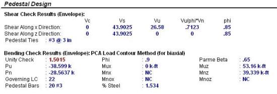
RISAFoundation will design the longitudinal and shear reinforcement for rectangular pedestals. This information is presented in tabular form on the Footing Pedestal Results Spreadsheet and in the Footing Detail Report.

Click on the image to enlarge it
Pedestal Flexure
For flexure, RISAFoundation uses a rectangular stress block. For biaxial bending situations, the load contour method is used. RISAFoundation does not account for slenderness effects.
For flexure design, RISAFoundation presents the required longitudinal reinforcement, assuming an equal distribution of bars around the perimeter of the pedestal. Supporting information includes the axial and bending contributions to resistance Pn, Mnx and Mnz. The total factored axial and bending loads Pu, Mux and Muz are also listed. The contour method beta factor and Mnox and Mnoz are given, with the moments representing the nominal uniaxial bending capacity at the axial load Pn. Finally, the Phi factor and the resulting unity check (demand vs. capacity) ratio is given.
Note that for vertical reinforcing design, RISAFoundation will meet the provisions of the ACI 318-14 Section 16.3.4.1 (ACI 318-11 Section 15.8.2.1) which states that in pedestals you must have a minimum reinforcement of 0.5% of the pedestal cross section.
Pedestal Shear
For shear design in either direction, RISAFoundation presents the required tie spacing. Also given are the concrete and steel contributions to resisting shear Vc and Vs along with the total factored load, Vu. Finally, the Phi factor and the resulting demand vs. capacity ratios are given.
Pedestal Punching Shear
Punching shear is calculated for a perimeter at a distance d/2 from the pedestal all the way around the pedestal. The soil bearing profile is integrated, minus the volume bounded by this perimeter, to obtain the total punching force to be resisted. For cases where the pedestal is near a corner of the footing, RISAFoundation considers the punching perimeter to extend out to the footing edge if the pedestal is within a distance d from the edge of the footing.
RISAFoundation presents the Vu and Vc values for punching and one-way shears, as well as the shear demand vs. capacity ratio. As long as this ratio is less than 1.0, the footing is adequate for the shear demand.
Stability Results
RISAFoundation will check the stability results for overturning and sliding. This information is presented in tabular form on the Stability tab of the Footing Results Spreadsheet and graphically in the Footing Detail Report.

Click on the image to enlarge it

Click on the image to enlarge it
Overturning Check
Overturning calculations are presented, as shown in the figures above. For all service combinations, both the overturning moments and the stabilizing moments are given, along with the calculated safety factor.
Overturning moments are those applied moments, shears and uplift forces that seek to cause the footing to become unstable and turn over. Resisting moments are those moments that resist overturning and seek to stabilize the footing. The overturning safety factor (OSF) is the sum of resisting moments divided by the sum of overturning moments. Most codes require that this factor be greater than 1.5. OSF calculations are based on the service load combinations only and are calculated in both the X and Z directions.
Overturning results from applied moments, applied shears and the summation of all these forces become the overall “overturning moment”.
- The OSF is calculated separately in both the X and Z directions as resisting moment / overturning moment. Overturning is evaluated about all edges of the footing and the worst case in each direction is reported.
- The width and length of the footing are only increased or optimized to prevent stability check failures if the "Optimize Footings" check box on the Concrete tab of the Model Settings has been checked.
- For Safety Factors greater than 1000, the footing is stable and the program will report 'NA' as the result.
Sliding Check
RISAFoundation provides sliding checks for all of the service combinations.
The applied forces and resisting forces, due to friction and passive soil resistance, are calculated and displayed. The final result is a sliding ratio of resistance vs. applied force that indicates a footing susceptible to sliding when the ratio is less than 1.0.
Concrete Bearing Check
The concrete bearing and demand/capacity ratios for each design combination are presented.
IMPORTANT: These concrete bearing checks are only based on the vertical applied loads, i.e. bending effects that increase or decrease bearing area and pressure are not considered.
The Concrete Bearing Check in RISAFoundation checks whether the footing concrete is adequate to resist the vertical loads imposed on the pedestal. These calculations are per ACI 318-14 Section 22.8 (ACI 318-11 Section 10.14). The results are presented as the demand vs. capacity ratio in the Detail Report.