Wall Footing Definitions
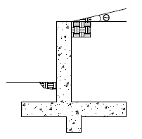
Wall footings consider soil loading and exterior loads for the concrete design of the wall stem and footing. The soil and exterior loads are also considered for overturning and sliding serviceability.
- For more information on modeling requirements, see Wall Footings - Modeling.
- For more information on calculation details, see Wall Footings - Design.
- For more information on the output, see Wall Footing Results.
Here we will explain the Wall Footing Definitions Spreadsheet and Wall Footings Spreadsheet. Both can be found on the Data Entry section of the Explorer toolbar or from the Data Entry drop-down on the Spreadsheets tab of the ribbon. Note that you can have multiple wall footings in a given project that may require multiple definitions.
The Wall Footing Definitions Spreadsheet and Wall Footings Spreadsheet are always synchronized. Making changes from one will update the other.
- See Wall Footing Definition Editor for more about how this information can be created from a graphic dialog.
- Items with an '*' in the following sections are only applicable for retaining walls, not strip footings.
General Tab
The following inputs can be made on the General tab of the Wall Definitions spreadsheet for wall footings:

Click on image to enlarge it
Label
This label provides a unique name for each wall footing definition. Clicking the  (ellipsis) button will open the Wall Footing Definition Editor. See below for more information on this dialog.
Wall Type
This allows you to choose between a retaining wall element and a strip footing element. See the Wall Footings - Modeling topic for more information on this.
Wall Const
This allows you to choose between a concrete or masonry retaining wall.
Wall Material
This is the wall material for the wall. If a concrete wall is selected, the concrete materials will be available. Similarly, masonry materials will be available when a masonry wall has been selected.
Foot Material
This is the concrete material for the footing.
Wall Height
This is the wall height from the top of the footing.
Soil Height
For retaining walls, this is the height of the backfill behind the wall taken from the top of the footing. For strip footings, this is the soil height on both sides of the wall above the footing.
Water Height*
This is the height of water behind the wall taken from the base of the footing. If this is input as zero (fully drained condition), then the water table will be assumed to occur below the bottom of footing or shear key.
Propped?*
This defines whether the top of the wall is propped. If the wall is propped, it is assumed the base is also restrained laterally and sliding and overturning checks for the wall are omitted.
Foot Restrained?*
This defines whether the bottom of the footing is restrained laterally (i.e. a basement slab is poured adjacent to the wall). If so, then the sliding check will be omitted.
Wall/Foot Continuity?*
This defines whether the wall and footing are assumed to be monolithic. If the wall and footing are monolithic (the Yes option), then we will not do a shear friction check for the dowels from the footing to the wall. If the wall and footing are not monolithic, then we will do a shear friction check. Smooth versus rough defines whether the footing at the location where the wall is poured has been intentionally roughened or not. This affects the shear friction calculation. For more information, see Shear Friction Check in the Wall Footings - Design topic.
Foot Dowels*
The number of layers defines whether there are dowels in both faces of the wall, or only the interior face (soil face). This input is only required if the footing and wall are NOT monolithic. If that is the case, then the shear friction check at the base of the wall requires an area of steel for the dowel bars. The program assumes that the dowels from the footing into the wall will match the wall reinforcement and calculates Avf accordingly.
Geometry Tab
The following inputs can be made on the Geometry tab of the Wall Definitions spreadsheet for wall footings:

Click on image to enlarge it
Wall Thickness
For concrete walls, it is possible to batter the wall. This thickness excludes the battered portion and would be the thickness at the top of the wall.
For masonry, this field is the block nominal thickness and must be set to 4, 6, 8, 10 or 12 inches. The program will subtract 3/8" from this value to get the actual thickness. This value is used, along with the value of grout / bar spacing, to determine the effective thickness of the wall. The effective thickness is based on table B3 of the Reinforced Masonry Engineering Handbook, by Amrhein, Copyright 1998.
Foot Thickness
This is the footing thickness.
Toe/Heel Length
This is the length of the footing from the outer/inner face of the wall.
Key Width/Depth*
These are the dimensions of the shear key, if there is one. If either of these dimensions is zero, then no key will be considered.
Key Offset*
This is the offset of the key from the inside (soil) face of the wall. A positive dimension will move the key in the heel direction. A negative dimension will move the key in the toe direction.
Wall Batter?*
This allows you to slope the toe face of the wall, the heel face or both.
Toe/Heel Batter*
If you've chosen to batter the wall from the Wall Batter? section, this is where you can define the batter dimension. This value is an additional thickness from the Wall Thick entry, at the base of the wall.
Soil Tab
The following inputs can be made on the Soil tab of the Wall Definitions spreadsheet for wall footings:

Click on image to enlarge it
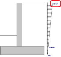
Method (Rankine or Coulomb)*
Here you have the choice of how you want lateral earth pressures calculated. Note that if you want seismic forces applied to your retaining wall, Coulomb must be selected.
- Calculations for soil pressures for both methods are defined in Wall Footings - Design.
- Seismic forces are described in Wall Footings - Design.
Gamma Heel/Gamma Toe
These are the soil densities on both the heel and toe sides of the wall for a retaining wall. For a strip footing, the Gamma Heel value is used for both the heel and toe.
Phi Heel/Phi Toe*
This is the internal angle of friction of the soil on both the heel and the toe sides of the wall. This is used, along with the backfill angle, in determining the lateral force coefficient (K). Note that there is a K input field. If this field is input, then we will override the calculation and simply use the input K value. For more information, see Soil Considerations in the Wall Footings - Design topic.
K Lat Heel/K Lat Toe*
This allows you to directly input the soil lateral force coefficient, K, for the soil on the heel and toe sides. You can leave this blank and the program will calculate K for you, using the Phi and Backfill Angle values. For more information, see Soil Considerations in the Wall Footings - Design topic.
Delta Wall*
This is the wall friction angle. It is used only if Coulomb is set for the Lateral Pressure Method. For more information, see Soil Considerations in the Wall Footings - Design topic.
Backfill Angle*
This is the slope angle of the backfill on the heel side from horizontal. A negative slope is not allowed.
Heel Surcharge*
This is a vertical surcharge pressure on the soil adjacent to the heel side of the wall and is always considered in the LL load category.
Toe Depth*
This is the soil depth above the top of footing on the toe side of the wall. If this is set to zero, then the soil level will be assumed at the bottom of footing elevation. Thus, if there is a shear key, you can consider the passive pressure only on the key.
EQ Max*
This is used for seismic loading and, if input, would define the maximum earthquake pressure at the top of an inverted earthquake pressure diagram. If this value is blank, the program will use Kh and calculate the seismic forces per the Mononobe-Okabe formulation. Seismic forces are described in Wall Footings - Design.
Kh*
This is the design horizontal ground acceleration (in units of g). This is an input into the Mononobe-Okabe seismic force calculation method. For more information, see Wall Footings - Design.
Gamma Sat/Phi Sat Heel/K Lat Sat Heel*
These are the soil parameters in the saturated portion of soil and are only considered if the water height is greater than zero. If K Lat Sat Heel is left blank, the program will use the Phi Sat Heel and the Backfill Angle to calculate K. For more information, see Soil Considerations in the Wall Footings - Design topic.
Wall Tab (Conc)
This tab is only used if your wall is made of concrete to define reinforcement parameters.

Click on image to enlarge it
Location
This defines whether you have a single layer of reinforcement or bars at each face.
Int Bar and Ext Bar
This defines the vertical bar on the interior (soil) and exterior faces of the wall. If you have defined a single layer of reinforcement, then the Ext Bar field will not be used.
Min/Max Int and Ext Bar Space
The program will design the vertical reinforcement spacing based on these guidelines. If you want the reinforcement to be at an exact spacing, enter that spacing as both the min and max in order to force the desired spacing.
- If you have a cantilevered wall, the exterior bar spacing design will be designed solely to meet minimum requirements.
- If you have defined a single layer of reinforcement, then the exterior min and max spacing will not be used.
Bar Inc
This is the spacing change increment that the program will use for design. If the maximum spacing does not work, the spacing will drop by this increment and be checked again. The program will work its way down until it reaches a spacing that meets all reinforcement requirements.
Int and Ext Cover
These are cover dimensions for the interior (soil) and exterior faces of the wall. If you have defined a single layer of reinforcement, then the exterior cover will not be used.
Hor Bar Size and Hor Bar Spacing
This defines the bar size and spacing of the horizontal bars in the wall. The program will check that these bars meet minimum requirements.
Outer Bars
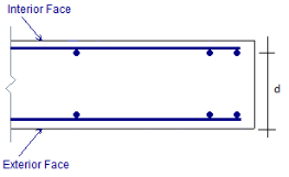
This defines whether the vertical or horizontal bars in the wall are nearest the faces of the wall. This affects the "d" calculation for the wall. If you have defined a single layer of reinforcement, then this field will not be used and it will be assumed that the vertical bar is nearest the inside (soil) face.
The images below are a section cutting horizontally through the wall. In this first image, Horizontal outer bars have been specified.
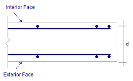
In this second image, Vertical outer bars have been specified.
Vertical
Wall Tab (Masonry)
This tab is only used if your wall is made of masonry to define reinforcement and design parameters.

Click on image to enlarge it
Block Grouting
This option defines how the wall is grouted. If Partially Grouted is chosen, the spacing of grout will be based on the Bar Spacing Min/Max.
Reinforced
This defines whether the wall is reinforced or not. Note that if the wall is unreinforced, the program will also consider the wall ungrouted.
Wall Area Method
This option defines where the wall area is taken from. The NCMA option pulls the An value from the NCMA TEK 141B document. The RMEH option pulls the "Equivalent Solid Thickness" value from Table B-3a and B-3b from the Reinforced Masonry Engineering Handbook, James Amrhein, 5th edition copyright 1998.
Research on these two methods of calculating the area for a masonry wall found that the two methods produce very different results. The NCMA values assume face-shell mortar bedding and web bedding around grout-filled cells. The RMEH values assume full mortar bedding (both face-shells and all webs). The Amrhein values also appear to average in the area of horizontal bond beams, as well. This would make the area conservative for a self-weight calculation, but unconservative for stress calculations. With these considerations in mind, the program will default to using the NCMA option.
For more information on this, see Masonry Wall Considerations in Wall Footings - Design.
Bar Size
This is the main vertical bar size that will be used for design.
Bar Space Min/Max
This allows you to give a maximum and minimum bar/grout spacing. If you give a range between the max and min, the program will optimize the reinforcement spacing according to code check requirements.
Bar Placement
This defines how the reinforcement is placed in the wall.
-
Center will put a single bar centered in a given cell.
-
Non-Center will put a single bar non-centered in a given cell.
-
Each Face will put reinforcement on both faces of a given cell.
-
Staggered alternates the bars on either face along the length of the region.
Cover
Allows you to specify the distance from the exterior of the masonry block to the extreme fiber of the reinforcement. The default cover value is defined as Min. The Min input will use the governing provision between the following two sections of the specification:
- Section 6.1.3.5 states a minimum distance between the inside of the face shell and the reinforcement. RISA is conservative and always assumes this to be 1/2". Thus, the cover calculated in this fashion = tfaceshell + 1/2"
- Section 6.1.4 requires a cover dimension = 1-1/2" or 2" depending on bar size and whether the masonry is exposed to weather. In the program, this is always assumed to be 1-1/2".
Thus, the Min term will create a cover equal to the maximum of tfaceshell + 1/2" OR 1-1/2".
For any other cover you wish to impose, simply overwrite the Min value with your value. If using the Non-Center option, the cover will always be from the +z local axis face of the wall.
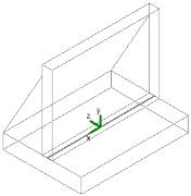
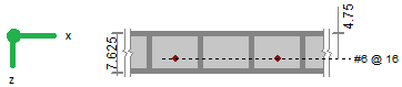
For example, let's assume the wall shown in the first image below is using the "Non-Centered" reinforcement and the cover is set to 2.5". The second image shows exactly where this bar is located in the wall (d = 7.625" - 2.5" - 3/8" = 4.75").
|
|
The actual "d" used in design will depend on the governing direction of loading. If load is applied in both out-of-plane directions to the wall, then it is possible that a lower level of loading can produce a higher code check because the "d" is smaller in one direction than the other.
If a non-sensical value is defined (i.e. one where the bar does not fall inside of the block core), then the program will give an error in the results and place the reinforcement just inside the faceshell of the block.
Mortar/Cement Types
Allows you to specify the type of mortar/cement in the wall. This affects the modulus of rupture (flexural tensile stresses) from Tables 8.2.4.2 and 9.1.9.2.
Footing Tab
The footing tab contains the reinforcement parameters for your wall footing.

Click on image to enlarge it
Location
This defines whether you have a single layer of reinforcement or bars both top and bottom.
Bot Bar and Top Bar
This defines the bottom and top bar sizes in the footing. If you have defined a single layer of reinforcement, then the Top Bar field will not be used.
Min/Max Bot and Top Bar Space
The program will design the main footing reinforcement spacing based on these guidelines. If you want the reinforcement to be at an exact spacing, simply enter that spacing as both the min and max in order to force the desired spacing. If you have defined a single layer of reinforcement, the top min and max spacing will not be used.
Bar Inc
This is the spacing change increment that the program will use for design. If the maximum spacing does not work, the spacing will drop by this increment and be checked again. The program will work its way down until it reaches a spacing that meets all reinforcement requirements.
Top Cover and Bot Cover
These are cover dimensions for the footing. If you have defined a single layer of reinforcement, the top cover dimension will not be used.
Long Bar Size and Long Bar Spacing
This defines the bar size and spacing of the longitudinal bars in the footing. The program will check that these bars meet minimum requirements.
- The program does not consider two way bending. This reinforcement is only for non-strength requirements.
Wall Footing Definition Editor
The Wall Footing Definition Editor enables you to create or modify wall footing definitions in a graphical way. This editor automatically updates any information input into the Wall Footing Definitions Spreadsheet.
-
Keep in mind that this dialog has multiple tabs. Make sure to fill out the information on all relevant tabs before clicking OK.
|
Click on image to enlarge it
|
Click on image to enlarge it |
|
General/Geometry tab for Retaining Walls |
General/Geometry tab for Strip Footings |
|
Click on image to enlarge it
|
Click on image to enlarge it
|
|
Soil tab (not applicable for Strip Footings) |
Wall Details tab (applicable for Concrete Retaining Walls and Strip Footings) |


|
Click on image to enlarge it |
|
Footing Details tab |

Accessing the Wall Footing Editor
To access this editor, you can click the (ellipsis) button on any tab in the Wall Footing Definitions Spreadsheet.

Click on image to enlarge it
This dialog can also be accessed from the Properties panel, as well.

Click on image to enlarge it