Adjust the Viewpoint (3D View)
Adjusting the Viewpoint refers to the ways you can modify a 3D View. An explanation of the features for adjusting the view and how to use each one is described below.
Features to Adjust the viewpoint in a 3D View
Zoom Features
There a two methods for zooming: you can simply use your mouse wheel, or use the Zoom tools on the View ribbon.
Use Your Mouse to Zoom
When you want to zoom in on the model to see more detail, or zoom out to view the whole model at once, it is often easiest to use your mouse wheel.
To zoom in or out using your mouse wheel:
-
Rotate the wheel forward to zoom in.
-
Rotate the wheel backward to zoom out.
Use the Zoom Tools
The Zoom tools found on the View ribbon can also be used for zooming in or out. First, choose the zoom state (In or Out) using the appropriate icon in the ribbon. Then, use your mouse to incrementally zoom. There are two additional Zoom tools: Zoom Extent and Zoom Box. These are explained below.

Click on the image to enlarge it
Zoom Extent Tool
This tool resets the view to show the full extents of the model. It is especially useful for resetting the model view after you’ve zoomed into a specific area.
To zoom to full model view:
- Click the Zoom Extents icon.
Zoom In Tool
This tool sets the zoom state to “in” so that each time you click your mouse button, the model view is enlarged.
-
Click the
 Zoom In icon on the View ribbon.
 -
Click anywhere in the model (3D View Window) to enlarge the model view.
-
Repeat Step 2 until the desired view of the model is reached.
Zoom Out Tool
This tool sets the zoom state to “out” so that each time you click your mouse button, the model view is reduced.
-
Click the
 Zoom Out icon on the View ribbon.
 -
Click anywhere in the model (3D View Window) to reduce the model view.
-
Repeat Step 2 until the desired view of the model is reached.
Zoom Box Tool
This tool lets you select a specific area to zoom into by drawing a box around the area.
To zoom into a specific area of the model:
-
Click the
 Zoom Box icon on the View ribbon.
 -
In the model view, click on one point and hold your mouse button down as you drag down to the opposite corner, creating a box around the area you want to zoom into.
-
Let go of the mouse button.
The view automatically zooms in to the boxed area.
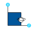
Pan the View
The Pan feature lets you drag the model view to the edges of the 3D View window. You can accomplish this by using one of two methods: your mouse scroll wheel, or the right-click menu.
Pan Using Your Mouse Wheel
To pan the model view using your mouse wheel:
-
Click and hold the mouse wheel button to trigger the dynamic pan feature.
You’ll see a
 panning icon appear, indicating that you are in panning mode and can begin dragging. You can drag the model view in any direction.
 -
While still holding down the mouse wheel, drag the model view in the direction you want to move it.
-
Release the mouse wheel when the model view is placed where you want it.
- If you do not have a mouse wheel you can use the right-click menu to pan the view.
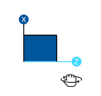
Pan Using the Right-Click Menu
To pan the model view using the right-click menu:
-
Right-click anywhere in the model view window.
-
Choose Pan from the menu that appears.
You’ll see the
panning icon appear, indicating that you are in panning mode and can begin dragging. -
Click and hold your left mouse button and drag the model view in the direction you want to move it.
-
Release the mouse button when the model view is placed where you want it.
-
To turn off panning mode, click the right-mouse button.
Snap to a View
To snap to an isometric or planar view of the model:
-
Click the Snap button at the top of the 3D View window that corresponds with the view you want.

Note that you can add your own custom snap view to the toolbar. When doing so, the current view is saved with the name you provide and added to the end of the toolbar.
Alternatively, you can right-click in the existing 3D View and select Add New 3D View.
(Optional) To add a custom snap view:
-
Click the down arrow on the Snap toolbar.

-
Click the
 ellipsis button that appears.
The Snap Views window opens.
-
Click Add.

Click on image to enlarge it
An Add Snap View window opens.
-
In the Snap View Label box, type a name for the new snap view.
-
Click Save.

Click on image to enlarge it
The new snap view is saved to the end of the Snap toolbar, as shown below, and you are returned to the Snap Views window.
-
Click Close to close the Snap Views window.


Rotate a View
There are two methods for rotating a view: click, or drag. An additional feature lets you quickly reset the model’s rotation to its original, default position.
As you rotate a view, the global X-Z axis orientation is shown by the orientation of the Navigation Icon.
Click to Rotate
To use the click method to rotate a view:
-
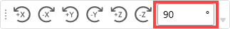
Click the rotate icon that corresponds to the rotation direction you want to use.
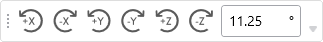
You can also change the rotation angle by entering a different degree magnitude. This affects the rotation of the model as you click to rotate.
-
(Optional) To change the rotation angle:
-
Type the degree magnitude in the box, as shown in the following image.
-
Click the rotate icon that corresponds to the rotation direction you want the model rotated.
The model is set rotated by the degree you’ve entered and the orientation of the Navigation Icon changes to reflect the angle and degree change.
-
Drag to Rotate
You can use one of the following drag methods to rotate the model view:
- While holding down the SHIFT key, press the mouse wheel to dynamically rotate the structure. For more information, see Dynamic View Controls.
-
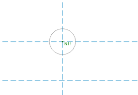
Click and drag the Navigation Icon to change the rotation of the model.
Default Rotation Click and Drag 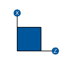
-
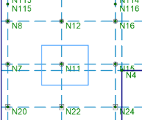
Use a global axis to rotate the view about one of the global axes by hovering over the axis until it turns blue. Then click and drag to change the rotation of the model.
 Note: If you hold down the SHIFT key while rotating the model using the individual axis, the model only rotates at 45 degree increments around that axis.
Reset Rotation to Default
Double-click in the Navigation icon to reset the rotation of the model view to the default isometric view position.
3D View Display Options
Each 3D View has several display options located at the top of the view; Display Loads, Display Results and Display Deflection.

Display Loads
The Display Loads icon lets you display loads in the model view.
To show loads in the model view panel:
-
Click the Display Loads icon to toggle the display of loads.
-
Click the Type down arrow and choose whether you want to display loads based on Load Category or Load Combination.
-
Click the
 down arrow in the second box and choose which load category or combination is shown in the view. This box not active when you choose Envelope from the Type drop-down menu.
See Model View Settings for more control over the display of loads.
Display Results
The Display Results icon lets you display color-coded results in your model view.
To show results:
- Click the Display Results icon.
- Click the Type down arrow and choose whether you want to display color coded results based on Load Combination or Envelope.
-
When Load Combination is selected, Click the
down arrow in the second box to choose which Load Combination results are to be colored coded in the model view. This box not active when you choose Envelope from the Type drop-down menu.A color legend appears and color-coded results based on your choices appear in the model view.
For more information on how to control the display of results, see Results View Settings.
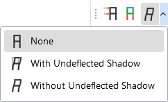
Display Deflection
The Display Deflection icon lets you display the deflected shape in your model view; with or without an undeflected shadow.
To show the deflected shape:
-
Click the Display Deflection icon.
-
(Optional) Click the down arrow to choose whether to view the deflected shape with or without an undeflected shadow (as shown in the following image).
The model’s deflected shape is displayed.