Punching Shear Design
Punching shear calculations are provided for columns/pedestals that land on concrete slabs. The following contains more detailed information on those calculations in RISAFoundation.
Punching Shear Basics
Punching shear is a phenomenon where a concentrated force on a slab causes a shear failure cone that "punches" through the slab.
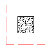
Punching shear calculations require a demand value and a capacity value. Many hand calculations will consider a punching shear force against a punching shear capacity. This works if only shear force is present, but is insufficient if a moment is occurring on the column/pedestal. Thus, a stress demand/stress approach is taken. The applied shears and moments, along with the shape of the punching shear failure cone, are used to calculate a maximum punching shear stress.
Punching Shear Calculation Values
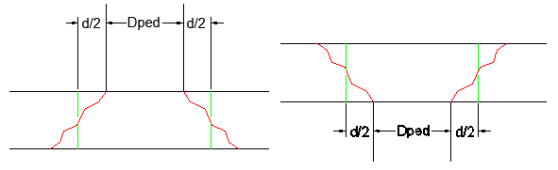
Effective Depth, d
The effective depth of the slab is used to define the punching shear perimeter at a distance of d/2 beyond the edge of the column/pedestal.
The effective depth is based on the smallest depth to centroid of reinforcing for the Design Strips that encompass the pedestal. In cases where no design strips are defined at the pedestal location, the program will assume the bar size and cover specified in the first rule defined in the Design Rules Spreadsheet.
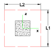
L1 and L2
L1 and L2 represent the length of the critical section along the local axes. This value is used to define the punching shear perimeter as well as how much of the moment is transferred by eccentricity of shear (as opposed to the portion transferred by flexure).
Polar Moment Ixx and Polar Moment Izz
The polar Moment is a property (Jc) of the critical section which is analogous to polar moment of inertia about the local yy axes. This value is used to determine the shear stress in the critical location due to unbalanced moment.
- This calculation is very different depending on interior, edge or corner punching shear cases.
- For further discussion and equations, refer ACI 318-14 Section 8.4.4.2.3 (ACI 318-11 Section R11.11.7.2) and Chapter 13-8 of the Reinforced Concrete Mechanics and Design textbook by MacGregor & Wight.
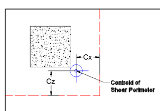
Centroid Location
The centroid gives the distance from the shear perimeter edge to the centroid of the shear perimeter. For an interior punching shear perimeter, this will always be L1/2 or L2/2. For edge and corner cases, this value is calculated as the moment of area of the shear perimeter/area of the sides.
Gamma xx and Gamma zz
This is calculated from the dimensions of the assumed punching shear perimeter. It represents the fraction of the unbalanced moment for each axis that is transferred by eccentricity of shear.
Total Stress
The Total Stress is the direct shear stress plus the shear stress due to moment. This calculation uses the geometry of the punching shear failure cone, along with the induced shear and moment forces, to come up with a maximum stress. This will always occur at one of the failure cone corner locations. For an example calculation, see the ACI 318-14 Section R8.4.4.2.3 (ACI 318-11 Section R11.11.7.2).
Phi*Vny
This represents the shear stress capacity of the slab, calculated based on the three ACI equations for two-way or punching shear capacity of the slab. For more information, refer to ACI 318-14 Section 22.6 (ACI 318-11 Section 11.11.7.2). When ACI 318-19 is selected, the shear strength of concrete (Vc) uses equations in Table 22.6.5.2. Note that an additional size effect factor λs is added in the equation. λs is a function of the effective depth of the slab 'd', and is calculated per Equation (22.5.5.1.3).
Minimum Slab Reinforcement at Punching Shear Critical Section
ACI 318-19 requires a minimum slab reinforcement at punching shear critical section if vuv>φ2λsλ√f’c per Section 8.6.1.2. As,min is calculated and presented in the punching shear result of columns under this condition. Please note that the reinforcement design in RISA programs for elevated slabs does NOT consider this requirement. Users need to consider separately the required additional slab reinforcement at punching shear critical sections to account for this code requirement. RISA provides the calculations of As,min per Equation (8.6.1.2) in the Detail Report.
Punching Shear Loading
Punching shear loading includes a direct shear component, as well as biaxial moments. It is these combined forces that are used to determine the punching shear stress and code check.
Direct Punching Shear
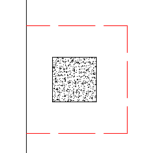
The direct punching shear demand is not exactly just the axial force in the Pedestal/Post. The area within the punching shear perimeter loading is assumed to pass directly into the support, so that force must be discounted.
This includes soil pressure resistance that occurs within the punching shear perimeter.
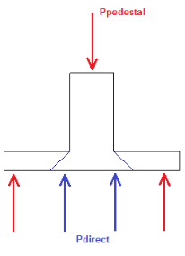
In the image above, the Vu demand equals Ppedestal - Pdirect
Moment Consideration
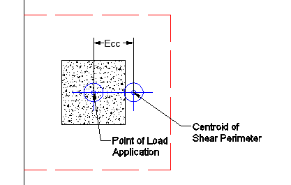
The moments used are also not necessarily just the moments directly from the Pedestal/Post. If the centroid of punching shear area is not the same as the centerline of the Pedestal/Post, then there will be an eccentricity that also adds/subtracts moment.
Take the edge punching shear situation, shown below:
The punching shear perimeter is to the right of the center of the Pedestal/Post location. This causes a moment in the punching shear calculation, even if a moment is not explicitly applied on the Pedestal/Post. This eccentricity is automatically accounted for in the punching shear stress calculation.
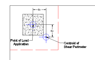
This same inherent eccentricity occurs in corner punching shear conditions. However, in this case, you get an induced moment in both local axis directions because of the centroid of shear perimeter location. This, similar to the edge condition, is automatically considered in the calculation of the maximum shear stress.
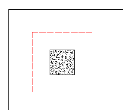
Finding the Controlling Case (Interior, Edge or Corner)
The program considers as many as nine different punching shear perimeters for each column in the model. We look at the interior, four edges and four corner cases and determine which configuration produces the largest code check and present that in the results.
For example, let's consider a Pedestal/Post that has an interior punching shear perimeter close to a corner.
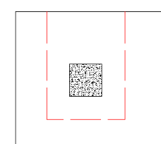
Here, the program will also check out any EDGE punching shear perimeter considerations. The two examples below would be the most likely ones for this given geometry.
However, these other two edge conditions would also be checked:
In most cases, these odd situations will not govern. However, large moments in a given direction can cause punching shear perimeters with larger areas to govern in specific cases.
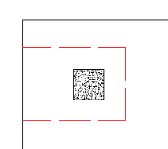
The program will also check out any CORNER punching shear considerations. The one below would be the most likely for this given geometry.
However, these other three corner conditions will also be checked:
Again, in most cases these odd situations will not govern. However, large moments in a given direction can cause punching shear perimeters with larger areas to govern in some specific cases.
Whichever configuration produces a maximum code check will be reported in the punching shear results.
- The punching shear perimeter lengths shown pictorially above will be shown as the L1 and L2 value for punching shear calculations.
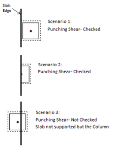
- To limit the total punching shear checks for a given column, we have added two caveats to the above behavior. For any of the four Edge or four Corner cases, the program will NOT perform a punching shear check if:
- The punching shear perimeter of any punching shear case is more than 50% larger than the minimum Edge/Corner punching shear perimeter.
- The punching shear perimeter of a punching shear case encompasses a column within it.
Corner vs Edge Controlling Cases
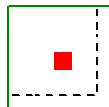
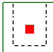
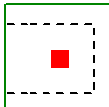
When the program tests all different cases to determine whether a corner or edge situation governs, it bases the controlling case on the maximum code check produced. There are instances where an edge case is governing that by inspection you might think would be governed by a corner case. See the images below:
| Corner Case | Edge Case 1 | Edge Case 2 |
|---|---|---|
|
|
|

|
|
|
In the two punching shear scenarios shown above, by inspection you would likely expect the corner condition to control over the edge ones. Punching shear capacity is based on a minimum of three equations in the ACI code. One of these equations has an alpha term in it, where alpha is smallest for a corner condition. If this equation governs, this would guarantee the corner condition would have the smallest capacity. However, if this equation does not govern, then these capacities may not be as different as you might expect.
Also, the demand portion of the equation will be different based on the geometry of the shear perimeter. It is possible that the edge cases produce a larger maximum stress than the corner cases.
In summary, our testing has shown that these non-intuitive scenarios where an edge controls over a corner can occur in some instances.
Other Punching Shear Considerations/Limitations
Punching Shear Perimeters That Cross Different Slab Thicknesses
It is possible to have different slab thicknesses within a single column/pedestal's punching shear perimeter. If there is a different thickness at any point along the punching shear perimeter, the program will use the thinnest thickness for the entire calculation. Also, there will be a warning message in the Detail Report when there is a different thickness detected. The L1 and L2 values used when calculating bo will use the depth at the location of the pedestal/column.
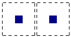
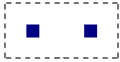
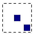
Pedestal/Post Groups
It may be possible for multiple, closely spaced pedestals/posts, to create a punching shear perimeter around the GROUP at a lower force level than would be observed by investigating one of the individual pedestals/posts. This is NOT currently considered in the punching shear code checks.
| Individual Punching Shear Perimeter | Group Punching Shear Perimeter |
|---|---|
|
|
Beams, Columns and Walls intersecting the influence area of a Pedestal/Post
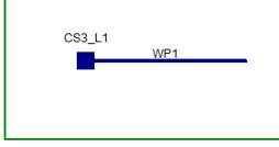
When a beam or wall is co-linear with the Pedestal/Post joint, the program will not provide a punching shear check on the Pedestal/Post. In these cases a code check of NC or "no calc" will be listed.
| Wall Co-Linear with a Column | Beam Co-Linear with a Column |
|---|---|
|
|
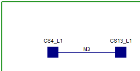
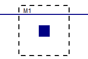
When a beam or column isn't co-linear with the column, but is located within the punching shear perimeter, then punching shear checks will still be performed. However, the calculations will not be influenced by the presence of that column or beam.
|
|
When the Pedestal/Post Local Axes Do Not Correspond to the Slab Geometry
The punching shear perimeters are always investigated with respect to the Pedestal/Post local axes. As shown below, there may be cases where these local axes do not correspond to the slab edge or corner geometry adjacent to that Pedestal/Post. In cases like these, it is possible for this to result in an artificially large assumed punching shear perimeter.
Edge Conditions
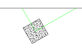
It is possible to get edge shear perimeters if either the slab edge is sloping, or a column local axis is rotated, as shown below:
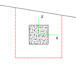
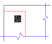
The program calculates this perimeter by drawing a line in the local axis direction along the centerline of the Pedestal/Post, as shown below:
From here, the program offsets this line on either side of the Pedestal/Post at a distance d/2 from the face. This produces a shear perimeter that looks like this:
Though this shear perimeter is not technically correct, it typically produces a nearly identical shear perimeter to the actual shear perimeter shown above.
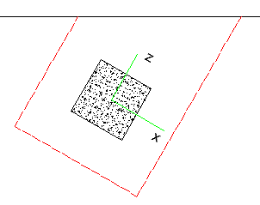
Corner Conditions
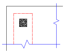
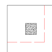
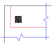
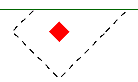
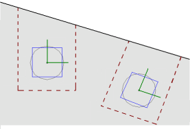
If either the slab edge is sloping, or the pedestal local axis is rotated, it is possible to get a corner shear perimeter. The program starts by trying to draw the full shear perimeter. In this case, we find that the shear perimeter has two sides that run into a slab edge. When this occurs, the program considers this a corner. There are two extremes for what the punching shear perimeter might look like for this case.
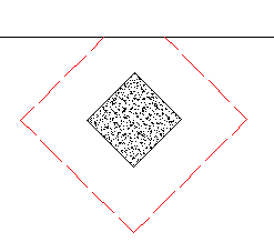
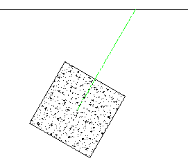
In reality, the punching shear is likely somewhere between these two extremes. What the program does here is similar to what is done for the edge case, except now this is done for both axes on one side only. Lines are drawn along the local axes of the Pedestal/Post until they reach the edge:
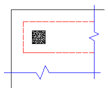
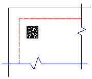
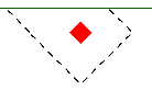
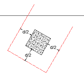
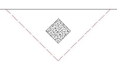
From here, the program offsets this line on the side away from the edge at a distance d/2 from the face. This produces a shear perimeter that looks like this:
![]()
The red line represents the L1 and L2 values the program uses to calculate punching shear perimeter. This perimeter doesn't actually hit the edge of the slab in our calculation, but this puts us in a situation where we are between the two extremes shown above and is a conservative approximation.
Using Equivalent Square Pedestal/Post
When calculating the punching shear perimeter for a round Pedestal/Post, the program always converts the dimension into an equivalent square of equal perimeter. This greatly simplifies the calculation of punching perimeters when close to an edge or corner.
For an example of this let's use a 12" diameter cross-section. The perimeter = Pi*Diameter = 37.7 in.
An equivalent square would have a side dimension = 37.7 in/4 = 9.424".
Thus, a 12" diameter round Pedestal/Post would be considered a 9.424" x 9.424" square for use in punching shear checks.
Punching Shear Reinforcement
The program currently does not allow for shear reinforcement. The only capacity considered for punching shear is the concrete itself. ACI 318-14 sections 22.6.6 (shear reinforcement), 22.6.9 (shearheads) and 22.6.8 (headed shear stud reinforcement) are not supported. ACI 318-11 sections 11.11.3 (shear reinforcement), 11.11.4 (shearheads) and 11.11.5 (headed shear stud reinforcement) are not supported.
Punching Shear Checks for Walls, Point Loads, and non-Concrete Columns
It is possible that punching shear failures can occur around walls (especially walls with a short length). It is also possible that punching shear failures can occur around point loads or non-concrete columns bearing on the slab.