 just once.
The sections that you create will be made up of basic shapes. You may double-click or drag-and-drop these shapes from the shape library to the workspace where you build the overall section. Working on the optional drawing grid you may reposition and resize the basic shapes to achieve the desired cross section.
The properties of the section may be continuously updated as you edit and refine your section. Once you have completed the section you may build a report for printing or save the file for future use in RISASection or for importing by RISA-2D, RISA-3D, and RISAFloor.
Sections are saved in files with a .nmsx extension by default. Multiple sections may be created and saved in one file, so you could have a file called STEEL.nmsx and one called CONCRETE.nmsx that store your steel and concrete shapes separately. You might name your files by project instead. That is completely up to you. All sections in a file are saved together by clicking just once.
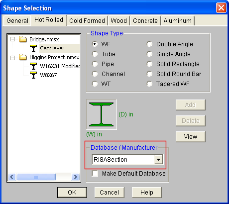
RISA-3D, RISAFloor, and RISA-2D look for all .nmsx files in the directory specified under Tools - Preferences- File Locations tab and simultaneously provide a list of all sections that exist in any of the .nmsx files. You can see which sections are available by clicking on the shape database within RISA-3D, RISAFloor, or RISA-2D.Then click on the General tab or the Hot Rolled tab (depending on which Material you selected in RISASection). Under Database/Manufacturer you can select RISASection. You will then be able to see the sections available to you. The list provided is of the names of the sections within each section file, so it is important to use unique, descriptive names for each section you create.
RISA-3D, RISA-2D, and RISAFloor look for all .nmsx files in the directory specified under Tools -Preferences -File Locations tab and simultaneously provides a list of all sections that exist in any of the .nmsx files. You can see which sections are available by clicking on the Shape Database button within RISA-3D, RISA-2D, or RISAFloor. Shapes that are designated as Hot Rolled Steel Material Type in RISASection will be found in the Hot Rolled tab of the Shape Database under the RISASection Database/Manufacturer.
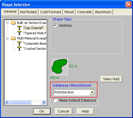
Shapes that are designated as General Material Type in RISASection will be found on the General tab under the RISASection Database/Manufacturer.
For additional advice on this topic, please see the RISA News website: www.risanews.com. Type in Search keywords: RISASection Integration.
The geometric properties are computed with the Polygon method. All closed shapes are represented by closed polygons. Curvilinear and circular shapes or edges are represented by several straight line segments. The properties of the overall shape are computed by geometric summation of the properties.
Accuracy of the Polygon Method
The above method for computation of geometric properties is generally adequate for shapes of usual dimensions and proportions. The method may lose some of it accuracy for very oblong shapes, highly curvilinear shapes and for shapes with very small or very large dimensions. These errors are introduced due to numerical round-off and may be more pronounced in the results of for second moment of area. Every closed shape is defined by a set of lines and its properties can be calculated by combining the properties of the component individual lines.
An iterative procedure is used to compute the plastic section modulus. The location of a "neutral axis" is determined that weighted areas above and below this line are equal. The plastic modulus is then computed as the moments of area about this neutral axis.
For all general shapes, besides circles and pipes, a full finite element solution of the torsional stress distribution is used. The section is meshed with finite elements and solved to determine J. For circles and pipes, the exact formula for torsional constant J is used.
When a section is designated as a pre-defined Hot Rolled shape type, additional torsional properties (i.e. Cw, Wno, Sw, etc.) are calculated in order for the shape to be exported for design code checks in RISA-3D, RISAFloor, or RISA-2D. These properties calculated using the approximate formulas from Formulas for Stress, Strain, and Structural Matrices by Walter D. Pilkey. This is done to save in solution time and to match as accurately as possible with hand calculation methods.
Note: These approximate formulas used to calculate Cw, Wno, etc. depend on the Flange Thickness and Web Thickness values. This means that if your shape is far from the pre-defined shape type, or if the orientation is different than the default, the thickness values can be calculated very wrong. Since the program cannot guarantee these values, we make them editable for the user. Simply highlight the value in the Properties window and type in another value. If you are changing these, it is important to also uncheck the Auto buttons associated with them because you will need to click the Solve button once more to recalculate the torsional properties with these values.
Most of the approximate formulas used to calculate the torsional properties are also dependent on the assumption that the section applies to thin-walled theory. To check this, RISASection internally checks that:
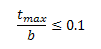
If the section does not meet this limit, you will be presented with a Warning Message at solution.
The properties of a built-up or composite section are computed by weighted summation and transformation of individual shape properties to the section centroid. The weight of the shapes is based on the relative ratio of the modulus of elasticity of individual shape to that of the base material.
For additional advice on this topic, please see the RISA News website: www.risanews.com. Type in Search keyword: Composite.
A Property Multiplier is used to specify the relative weight of the shape's Modulus of Elasticity in the overall section. It is the ratio of the Modulus of Elasticity of a particular shape to the Base Modulus of Elasticity (which may be edited in the Section Properties tab of the Options menu). This factor may be assigned a fixed value for each shape, or it may be computed automatically by the program as the ratio of the Modulus of Elasticity of the shape material and that of the Base Material.
Any positive, negative or zero value may be specified:
1 or a positive value = Solid or positive Shape
0 = Ignore the Shape in properties calculations
-1 or a -negative value = Void or hole or a negative Shape
Note that when using a negative value for a hole, you want to make sure that the negative property value that you use is the negative of the property multiplier that you are putting your hole onto. For example, if steel is your material and you are punching a hole into a solid section, you want your modulus of elasticity for your steel to be 29000 ksi and the modulus of elasticity for your hole to be -29000 ksi.
For additional advice on this topic, please see the RISA News website: www.risanews.com. Type in Search keywords: RISASection Void.
You may specify the property multiplier in one of two ways. Double-click a shape, in the workspace to open the editor and specify the modulus of elasticity and we will modify the property multiplier accordingly. Alternatively, click  to view the layout of all shapes currently in the section. The table also shows the multiplier for each shape, which you can modify manually.
The calculated Section Properties (described below) are listed on the lower right window. With the View Options on the Option menu you may have properties calculated automatically as you build and edit a section or manually by clicking  . Click
  to calculate the torsional constant J, which may not be calculated automatically. You may print the properties for the current section by clicking
  or create a report that contains multiple sections.
You may calculate transformed properties for composite sections that have shapes of different materials. To do this use the property multiplier to distinguish between the different material types.
Note:
These properties are calculated for all shapes, regardless of Material or Shape Type.
|
Property Label |
Description |
|---|---|
|
Total Width and Height |
Total overall width and height of the section. |
|
Centroid, Xo |
Horizontal distance from the global X-axis origin to the centroid of the section. |
|
Centroid, Yo |
Vertical distance from the global Y-axis origin to the centroid of the section. |
|
X-bar (Right and Left) |
Distance from the centroid of the section to the extreme right and left fiber. |
|
Y-bar (Top and Bot) |
Distance from the centroid of the section to the extreme top and bottom fiber. |
|
Area, Ax |
Total area of the section. |
|
Inertia, Ixx and Iyy |
Moment of inertia about the global X and Y axes. |
|
Inertia, Ixy |
Product moment of inertia. |
|
Torsional J |
Torsion constant. |
|
Sx (Top and Bot) |
Elastic section modulus of the extreme top and bottom fibers. |
|
Sy (Left and Right) |
Elastic section modulus of the extreme left and right fibers. |
|
rx and ry |
Radius of gyration about x and y. |
|
Plastic Zx and Zy |
Plastic section modulus about x and y. |
In addition to the properties above, the following properties may also be calculated. Their inclusion depends on the Material and Shape Type selection in the Section Information window.
|
Property Label |
Description |
|
Max Thick |
Maximum thickness of the section. |
|
Flange Thick |
Thickness of the flange. |
|
Web Thickness |
Thickness of the web. |
|
Leg Thickness |
Thickness of the leg of a single angle. |
|
Space |
Space in between the back to back legs of a double angle. |
|
Thickness |
Wall thickness (such as for a tube or pipe section). |
|
As-xx Def |
Shear deformation factor about the xx axis. |
|
As-yy Def |
Shear deformation factor about the yy axis. |
|
As-xx Stress |
Shear stress factor about the xx axis. |
|
As-yy Stress |
Shear stress factor about the yy axis. |
|
Shear Center, Xs |
Horizontal distance between the centroid and the shear center. |
|
Shear Center, YS |
Vertical distance between the centroid and the shear center. |
|
eo |
Distance from the outside web of a channel to the shear center. |
|
ro |
Polar radius of gyration about the shear center. |
|
rT |
Radius of gyration of a portion of the section including the upper flange plus 1/3 of the web area, taken about the X axis. |
|
rZ |
Radious of gyration about the Z axis (principal axes for single angles). |
|
Cw |
Warping constant for the section. |
|
Wno |
Normalized warping function at a point on the flange edge. |
|
Sw |
Warping statical moment. |
|
Qf |
Statical moment of the flange. |
|
Qw |
Statical moment of the cross section. |
|
Total Width (Top) |
Tapered wide flange top flange width. |
|
Total Width (Bot) |
Tapered wide flange bottom flange width. |
|
Flange Thick (Top) |
Tapered wide flange top flange thickness. |
|
Flange Thick (Bot) |
Tapered wide flange bottom flange thickness. |
Some of the additional calculated Properties offer a Auto checkbox in the Properties window.
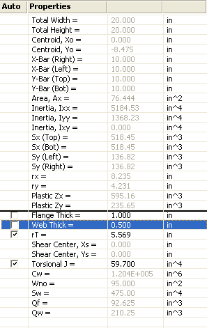
This checkbox controls which of the editable properties will be determined automatically per the shape graphic. RISASection will attempt to calculate these values upon solution, but because they are not always exact, you have the ability to overwrite the RISASection value with your own. Simply click on the value in the Properties window to highlight the entry and then type in your value.
The Auto checkbox controls whether or not these values will be re-populated if you click the Solve  button after overwriting these values. Please see the Editable Properties topic for a description of how RISASection approximates these values.