View Crack Width Contours

You can view the crack width contours using the Results View panel as well as the ADViewer.

To view crack width contours through the Results View panel:

  1. Run an Analysis.

  2. Design the Design Sections.

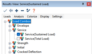
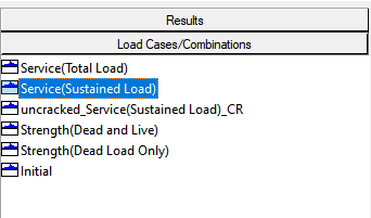
  3. In the Results View panel click on the Load tab and select a service combination you want to view the crack widths for.

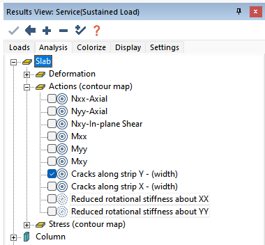
  4. Click on the Analysis tab, expand the Slab tree and expand the Slab Actions (contour map) tree.

  5. Select the Crack Along Strip X or Crack Along Strip Y result.

    Note: The crack width calculation is calculated for service combinations only. If you have another type of combination selected the crack width results shown in the image below will be unavailable to select.

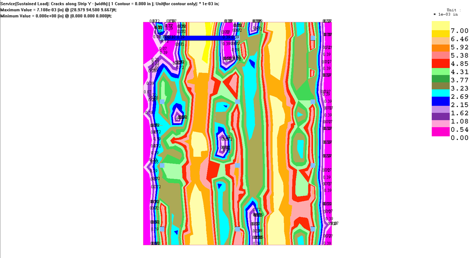
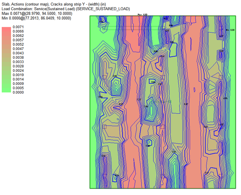
  6. The crack width contours will show on plan.

    Click image to enlarge

To view crack width contours through the ADViewer:

  1. Run an Analysis.

  1. Design the Design Sections.

  2. Go to Analysis>Analysis and click on the View Analysis Results icon to open the ADViewer.
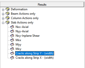
  3. In the Results panel select the Cracks Along Strip X or Cracks Along Strip Y result.

    Note: The crack width calculation is calculated for service combinations only. If you have another type of combination selected the crack width results shown in the image below will be unavailable to select.

  4. Click on the Load Cases/Combinations panel in the left windowpane.

  5. Select a service combination you would like to view the crack widths for.

  6. Click on the Display Results icon

  7. Click on the Color Contour icon to display the color contour result in the result viewer.

    Click image to enlarge