Assign Stiffness Modifiers to Components
Stiffness Modifiers can be assigned to slabs, beams, walls, columns and ramps in the model. Each component has a different set of stiffness modifiers. The components that have stiffness modifiers that can be assigned to them and the Definition of Component Stiffness Modifiers are listed at the end of this topic.
To Assign Stiffness Modifiers to Components:
-
Select the component or components within a single component type that you want to assign stiffness modifiers to.
Note: It is important to select only one component type at a time as each component type may have different modifiers associated with it.
-
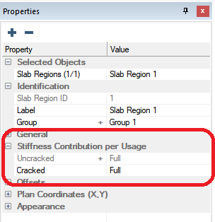
In the Properties Grid expand the Stiffness Contribution per Usage tree.
-
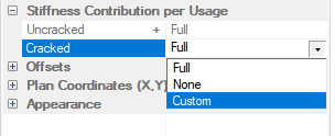
Click the Value Cell next to the Usage Case you want to modify the component’s stiffness for, and select Custom from the drop-down list.
Note: You can also choose NONE which will set all stiffness modifiers for the components to 0. When set to NONE the components do not contribute to the stiffness matrix.
-
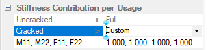
After choosing Custom the stiffness modifiers will unlock and be available for modification.
-
Set the value for each stiffness modifier to a value between 1 and 0.
-
Select the next group of components for the next component type you want to modify stiffness modifiers for and assign the stiffness modifiers in the same fashion.
-
Once all Stiffness Modifiers are defined for all Usage Cases we can now Analyze the Model Using Usage Cases.
Definition of Component Stiffness Modifiers
Slabs:
F11 and F22 are axial modifiers (PL/AE)
M11 and M22 are out-of-plane bending
Walls:
F11 is axial
F22 is in-plane shear
M11 is torsion/twisting on the wall
M22 is weak axis bending
Columns:
F11 is AE modifier for axial
M11, M22, and M33 are EI modifiers for bending about those axes
Beams:
F11 is axial
M11 is torsion
M22 is in-plane bending
M33 is "normal" bending
Ramps:
F11 and F22 are axial modifiers (PL/AE)
M11 and M22 are out-of-plane bending