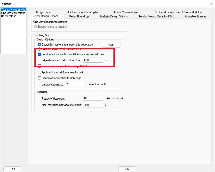
The option to consider critical sections outside the shear reinforced zone with a reduced octagonal-shaped critical section is given in the Criteria ribbon Shear Design options window.
Click on image to enlarge
ACI 318-14 Sections 22.6.4.2 and 22.6.6.1 apply. The following images show the octagonal-shaped section used in ADAPT-Builder for compliance with ACI 318-14 and later codes. Note this section shape can now also be used for designs performed using all ACI 318 versions supported by the program. The option is selected and turned on by default.
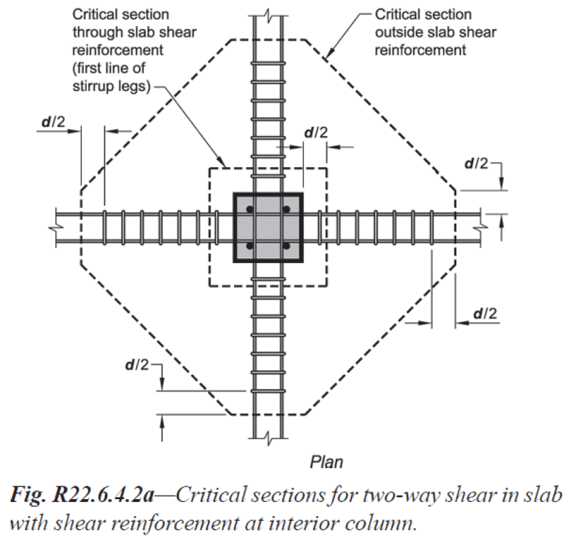
Interior Column Critical Section
Click on image to enlarge
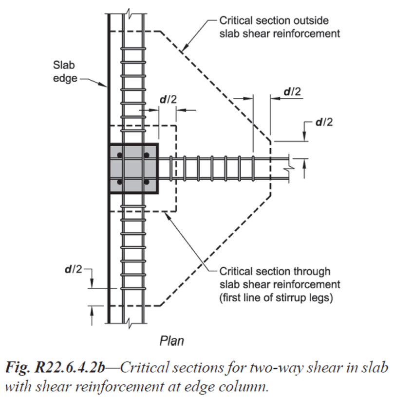
End/Edge Column Critical Section
Click on image to enlarge
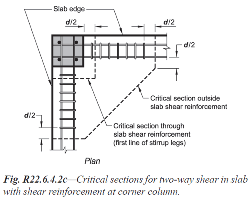
Corner Column Critical Section
Click on image to enlarge
When checking punching shear, the program checks a rectilinear critical section at d/2 from the face of the support. If reinforcement is required at this critical section, additional critical sections are checked at increments of d/2 (3d/4 if the option to Consider Increased Stud Spacing is selected) until no reinforcement is required. If the option to Consider critical sections outside shear reinforced zone is selected, the program will then check a reduced octagonal critical section at the same distance from face of support as the last rectangular critical section. Octagonal critical sections will then be checked at increments of d/2 (3d/4 if the option to Consider Increased Stud Spacing is selected) until no reinforcement is required.
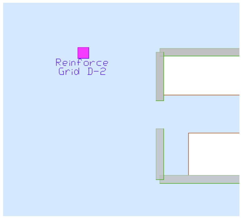
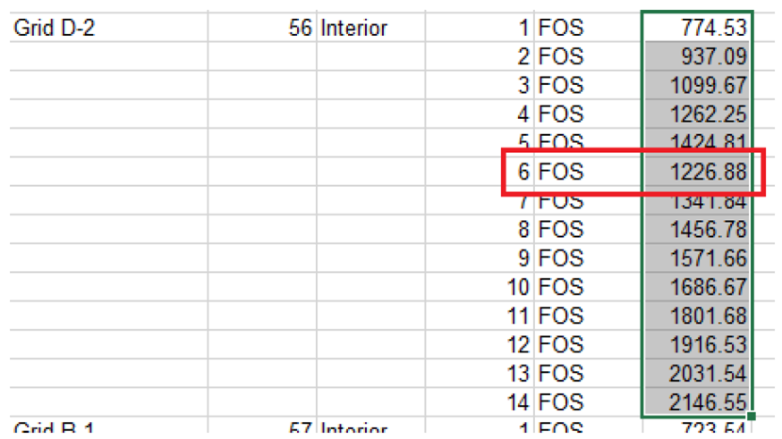
The distance from the face of support at which the octagonal critical sections begin is evident in the XLS output for punching shear in ADAPT-Builder. This can be viewed by going to the Reports ribbon Single Default Reports panel. Click on the Punching Shear icon and select XLS Reports→Punching Shear Report. There are two sheets within this report that dictate the location of the section shape change. These include the ‘Critical Section Geometry’ and the ‘As Required’ sheets. An example is presented below for an interior column located at Grid D-2. The first image is a graphical indication that this column requires reinforcement. Continuing into the details of the XLS report, the second image below shows the location at which the critical section area reduces. Note between critical sections 1 and 5 the area increases. Between sections 5 and 6 there is a decrease in area from 1424.8in2 to 1226.9in2. This indicates that section 6 is the first section checked as an octagonal critical section. Additional sections (8-14) are required to be checked with the same shape.
Click on image to enlarge
Click on image to enlarge
The image below shows the required area of steel for the same column at Grid D-2. Note that at critical section 5, where the rectilinear shape is used, the required As is calculated as zero. The next critical section, and all remaining in sequence, are those checked with an octagonal critical section.

Click on image to enlarge
You can also review the ‘Stress Check’ sheet to review the allowable stress reported. On this sheet there is clear indication given where the maximum stress is reported.