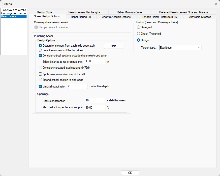
| One-way shear reinforcement |
Options for one-way shear number of legs are now defined in the Support Line Properties and the reinforcement size used is defined in the Preferred Reinforcement Size and Material criteria tab. Option is inactive in this window.
|
|
Punching Shear
|
Lets you choose the type of reinforcement you prefer for punching shear design, stirrups or shear studs.
-
Designed for moment from each side separately – This option calculates the punching shear two times, each time with the participation of moment from one of the principal axes only.
-
Combine moments of the two sides – This option adds the stresses due to the contribution of moments about both axes together for code check.
-
Consider critical sections outside shear reinforced zone – The option to consider critical sections outside the shear reinforced zone steps the critical section down to the reduced octagonal section and rechecks the need for reinforcement. ACI 318-14 Sections 22.6.4.2, 22.6.6.1 apply. See the Critical Sections Outside the Reinforced Zone topic for more information.
-
Edge Distance to rail or stirrup line – This option lets you specify the edge distance between the edge of column and stud rail or shear stirrups. This value affects the critical section length.
-
Consider increased stud spacing (0.75d) - This option, when checked, will apply two-way shear provisions for shear studs location and spacing limits as found in ACI 318-14 Table 8.7.7.1.2.
-
Apply minimum reinforcement for drift – This option, when checked, will apply two-way shear provisions related to minimum reinforcement for seismic drift as found in ACI 318-14 Section18.14.5.1. See the Minimum Reinforcement for Drift topic for more information.
-
Extend Critical Sections to Slab Edge – This option allows you to extend the critical section to the slab edge to take into account the concrete area truncated by the program when conditioning the column as an end/edge or corner condition. When the column is conditioned as end/edge or corner the program will ignore any concrete attributed to the face of column being omitted from the shear check.
Note: If a drop cap or drop panel is modeled at the column or the user has manually conditioned the column, the program will not extend the critical sections to the slab edge.
-
Limit Rail Spacing to X times the effective depth, where X is a value defined by you – This option allows you to have the program automatically limit the spacing between rails along a side such that the max spacing between rails will be X times the effective depth of the critical section. X by default is 2 but can be modified by you.
|
|
Openings
|
Lets you choose the options for detecting openings around the column to include in the shear check. When included, the program will reduce the critical section area used in the shear check to account for the opening. See the Detection of Openings for Punching Shear Check section of this help menu for more information.
-
Radius of detection – This setting is used to determine at what distance from the face of support openings will be detected and deducted from the critical sections. The input is based on a multiple of the slab thickness. Any opening that is within or intersected by this imaginary boundary is considered in the reduction of the critical perimeter.
-
Max. reduction per face of support – This setting means that if the opening projection lines that intersect the column face are more than 90% of the column face (or user-defined value), that side is considered as free edge.
|
|
Torsion (Beam and One-way Criteria)
|
Lets you chose the options for performing torsion design of beams within your model. Only available when ACI-2019 or ACI-2022 is the selected design code.
-
Disregard - This setting is used when no torsion design or threshold check is to be performed.
-
Check Threshold - This setting is used when you want to check if the torsional threshold has been exceeded or not only. Reinforcement design for Torsion will not be performed. After design of one-way or beam sections, view the results within the Results View panel Torsion Result section.
-
Design - This setting is used to design beams for torsion when the torsional threshold has been exceeded.The type of torsion design is chosen through the Torsion Type drop down menu. After the design of one-way or beam sections, view the results within the Results View panel Torsional Results section.
Options are:
-
Equilibrium - Uses the Equilibrium method of ACI-2019/22 22.7.3.1 designing for the factored torsional moment.
-
Compatibility - Uses the Compatibility method of ACI-2019/22 22.7.3.2 designing for a factored torsional moment no greater than the cracking moment.
|