Support Line Properties can be viewed and modified in either the Support Line Properties Dialog or in the Properties Grid. While both provide most of the same property settings, the Support Line window includes the ability to setup design section options. In addition the Design Section Tab allows you to review section geometry, reinforcement, and design data for each section along the support line. Found at the end of this topic are instructions for Modifying the Support Line Properties.
The Properties Grid includes a few settings not available in the Support Line item properties window. This includes the Stirrup Legs, Middle Strip, and Width Limits. The Stirrup Legs property defines the number of stirrup legs used in the one-way shear calculation of one-way and beam designated design sections. The Middle Strip option designates a support line as a middle strip support line. The Width Limits input allow you to limit the tributary width by designating a maximum width distance or by percentage of tributary that should be allocated to the column strip. If you need to modify these, you'll need to do so in the Properties Grid panel.
Click on image to enlarge
Support Line Properties Dialog:
To open the Support Line item properties window, double click a support line, or select a support line, and choose Item Properties from either the Modify or Model ribbon, or the Quick Access Tools toolbar.
Click on image to enlarge
Directly above the tabs of the Support Line window is a menu that includes a set of icons. These icons are explained in the following table.
Support Line Icons
| Icon | Label | Description |
|---|---|---|
|
|
Apply |
Applies any modified data in the window to the structural component. |
|
|
Rendering |
Opens the ADAPT Solid Modeling rendering window in which you can view a 3D render of the strip and make modifications to the strip geometry (idealized design tributary view), prior to exporting the strip to our ADAPT-PTRC software. Note: The Rendering option is only available if PTRC is selected when you log into ADAPT-Builder.
|
|
|
Write PT Data |
Creates an ADAPT-PTRC strip model file that you can open in ADAPT-PTRC. Note: The Write PT Data option is only available if PTRC is selected when you log into ADAPT-Builder.
|
|
|
Go to Design Summary |
Opens the ADAPT-BuilderSum (Summary) window in which you can view a summary of results for the selected support line. |
|
|
Cut |
Generates an elevation cut of the support line. The elevation image appears wherever you click in the model editor panel. If you do not click in the panel, the image does not appear. It is recommended to click in the area of the model editor panel that is away from the main model when creating these cuts for ease of viewing and deleting.
Click on image to enlarge |
|
|
Design Sections |
Generates an elevation cut for each design section along the support line. The images appear wherever you click in the model editor panel. If you do not click in the panel, the images do not appear. It is recommended to click in the area of the model editor panel that is away from the main model when creating these cuts for ease of viewing and deleting.
Click on image to enlarge |
|
|
Help |
Display a toolbar Help window that describes the function of each of the icons. |
The Support Line item properties window has five tabs that allow you to modify specific properties of a selected support line (General, Location, Design, Display and Design Section Options), one tab that allows you to review section geometry, reinforcement, and design data for each section along the support line (Design Sections), and one tab that allows you to set some basic properties (Properties) for the display of the support line. The following sections describe the support line property settings that can be found under each tab, and their related property setting in the Properties Grid panel.
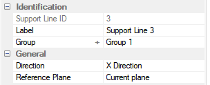
The corresponding inputs can be found in the Indentification and General trees of the Properties Grid when a support line is selected.
The following table provides a description for each of the Support Line item properties that can be found under the General tab.
General Support Line Properties
| Property |
Property Grid Tree |
Description |
|---|---|---|
|
# |
Identification > |
The internal identification number for the selected support line item. The Support Line ID can not be modified by the user. |
|
Label |
Identification > |
The name of the selected support line item to identify it by name in the model. The current name is displayed. To change the name:
|
|
Group |
Identification > |
Display the current group of the selected support line item. To change the group:
|
|
Direction |
General > |
Displays the direction of the of the support line item you've selected. To change the direction:
|
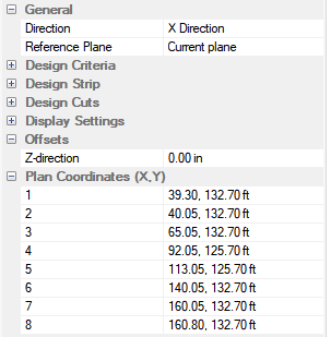
The corresponding inputs can be found in the General, Offsets, and Plan Coordinates (X,Y) trees of the Properties Grid when a support line is selected.
The following table provides a description for each of the Support Line item properties that can be found under the Location tab.
Location Support Line Properties
| Property |
Property Grid Tree |
Description |
|---|---|---|
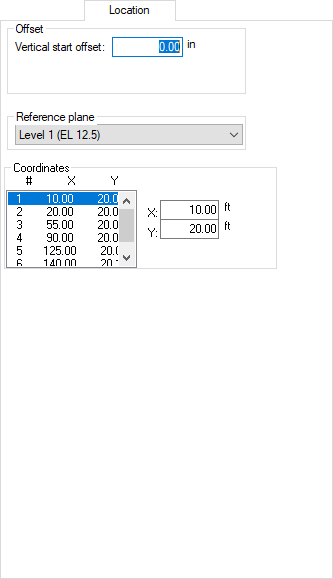
|
Vertical start offset |
Offsets > Z-direction |
Indicates the current offset value for the Z direction at the top of the support line. Positive downward. To change the offset value:
|
| Reference plane | General > Reference Plane |
Displays the support line's current reference plane and allows you to choose a different reference plane. To choose a different reference plane:
|
|
Coordinates |
Plan Coordinates (X, Y) |
Displays the current X, Y coordinates of the support line at the various points. To modify the coordinates at any of the points:
|
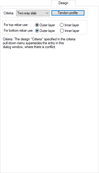
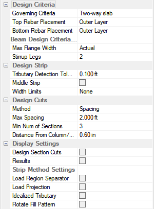
The corresponding inputs can be found in the Design Criteria tree of the Properties Grid when a support line is selected.
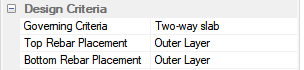
The following table provides a description for each of the Support Line item properties that can be found under the Design tab.
Design Support Line Properties
The corresponding inputs can be found in the Design Settings tree of the Properties Grid when a support line is selected.
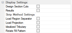
The following table provides a description for each of the Support Line item properties that can be found under the Display tab.
Display Support Line Properties
| Property |
Property Grid Tree |
Description |
|---|---|---|
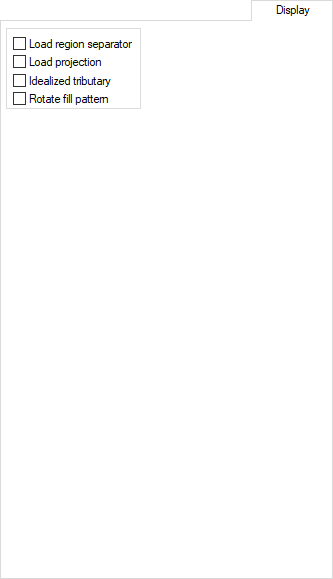
| Load region separator | Strip Method Settings > Load Region Separator |
When checked, the solid model of the design strip will show regions for load discretization for export to ADAPT-PTRC. If you modify the current choice within the item properties window, remember to click the
|
| Load projection | Strip Method Settings > Load Projection |
When checked, the solid model of the design strip will show discretized loads on the frame line for export to ADAPT-PTRC. If you modify the current choice within the item properties window, remember to click the
|
| Idealized tributary | Strip Method Settings > Idealized Tributary |
When checked, the solid model of design strip will show idealized tributary regions for each span for export to ADAPT-PTRC. If you modify the current choice within the item properties window, remember to click the
|
| Rotate fill pattern | Strip Method Settings > Rotate Fill Pattern |
When checked, the solid model of design strip hatching fill will be rotated. If you modify the current choice within the item properties window, remember to click the
|
The corresponding inputs can be found in the Design Criteria, Design Strip, Design Cuts, and Design Settings trees of the Properties Grid when a support line is selected.
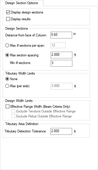
The following table provides a description for each of the Support Line item properties that can be found under the Design Section Options tab.
Design Section Options Support Line Properties
| Property |
Property Grid Tree |
Description |
|---|---|---|
| Display design sections |
Display Settings > |
When checked, the design sections are shown in the graphical view. If you modify the current choice within the item properties window, remember to click the
|
| Display results | Display Settings > Results |
When checked, the design section results are shown in the graphical view for the selected support line. If you modify the current choice within the item properties window, remember to click the
|
| Distance from face of Column | Design Cuts > Distance From Column/Wall Face |
Defines the distance from the face of the support where the first design section of a span of a support line is located. To modify the current distance:
|
| Max # sections per span | Design Cuts > Method (Number of Sections option) |
When this option is selected, it defines the maximum number of sections allowed to be generated per span. To modify the current maximum number of sections per span:
|
|
Max section spacing |
Design Cuts > |
When this option is selected, it defines the maximum spacing used to generate design sections within the span of a support line. To modify current maximum section spacing:
|
|
Min # sections |
Design Cuts > |
Only available when the Max section spacing option is selected. This property defines the minimum number of design sections to be generated within the span of a support line. To modify the current minimum number of sections:
|
|
Tributary Width Limits |
Design Strip > |
This option is available only when Middle Strip is NOT checked in the Design Strip section of the Properties Grid. There are three tributary width limits to choose from:
If you modify the current choice within the item properties window, remember to click the
Alternatively, the percent between spans property can be more efficiently assigned to support lines using the Dynamic Editor - Limits tab. |
|
Effective Flange Width (Beam Criteria Only) |
Design Criteria > Beam Design Criteria (where applicable) > |
This option applies only to "Beam" criteria. When checked, the program uses code-required effective flange width for Beam calculations. If selected, you can also determine if the program should exclude tendons and/or rebar outside of the effective flange width. When not checked, the program uses the full length of the design section for flange width. If you modify the current choice within the item properties window, remember to click the
|
|
Exclude Tendons Outside Effective Flange |
Design Criteria > Beam Design Criteria (where applicable) > |
Available only when Effective Flange Width (Beam Criteria Only) is checked. When checked, tendons outside of the effective flange are not included. If you modify the current choice within the item properties window, remember to click the
|
|
Rebar Outside Effective Flange |
Design Criteria > Beam Design Criteria (where applicable) > |
Available only when Effective Flange Width (Beam Criteria Only) is checked. When checked, rebar outside of the effective flange are not included. If you modify the current choice within the item properties window, remember to click the
|
|
Tributary Detection Tolerance |
Design Strip > |
Indicates the distance of construction lines used to create the tributary region. Use smaller distances to get a more refined tributary. To modify the current tributary detection tolerance:
|
The Design Sections tab displays design section information for the sections along the support line. Since this window includes design results, it is not viewable in the Properties Grid panel. Note that some information is available prior to the design of sections. After the design of sections, the remaining data will be populated. The Design Sections tab can be accessed by double clicking a design section along the support line or through the Item Properties icon in the Modify and Model ribbon or within the Quick Access Tools when a user has a support line selected.
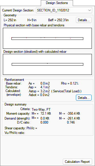
The following table provides a description for each of the Support Line item results that can be found under the Design Sections tab.
Design Sections Support Line Results
| Property Value(s) | Description | ||||||||||||||||||||||
|---|---|---|---|---|---|---|---|---|---|---|---|---|---|---|---|---|---|---|---|---|---|---|---|
|
Current Design Section |
Displays the ID for the design section whose information you are currently viewing. The section will be highlighted in the plan view to help identify the section on plan. With this particular setting, you can view the information for any of the design sections along the selected support line by either cycling through them using your mouse scroll button or using the down-arrow to select another design section to view information for. Both methods are described here. Using the Mouse Scroll Button This method allows you to quickly cycle through the various sections along the support line. To use this method:
Using the Current Design Section Down-arrow This method allows you to view a list of the sections along the support line and choose a different section to view the information for. To use this method:
|
||||||||||||||||||||||
|
Geometry |
Provides the basic geometry for the selected support line item. L = Length of the design section H = Maximum section height of the design section Beff = Effective Flange Width used in the design of the section if the Effective Flange Width option has been invoked. For additional settings and their details, click the Details button. |
||||||||||||||||||||||
|
Details (button) |
Opens a Design Section Details window that allows you to view more details about the Design Section and Idealized Design Section geometry. In this window you can see the physical properties of the section, the idealized properties and the difference between the two.
Click on image to enlarge The following table provides descriptions for each detail.
|
||||||||||||||||||||||
|
Geometry Physical section with base rebar and tendons |
Provides a graphical view of the design section with base rebar and tendons. Rebar placement is shown as blue dots while tendons are shown as red dots.
Click on image to enlarge Click on the graphical view to open it in a larger Design Section Zoom window. The zoom window displays an enlarged view of both the "Physical section with base rebar and tendons" and the "Design section (Idealized) with calculated rebar" graphical views. |
||||||||||||||||||||||
|
Geometry Design section (Idealized) with calculated Rebar |
Provides a graphical view of the Idealized Design Section and the area of reinforcement calculated by the program to meet minimum reinforcement and strength requirements of the code. Each area of rebar that is required to bring the design section up to code is indicated by a green (area of steel in top fiber) or red (area of steel in bottom fiber) dot.
Click on image to enlarge Click on the graphical view to open it in a larger Design Section Zoom window. The zoom window displays an enlarged view of both the "Physical section with base rebar and tendons" and the "Design section (Idealized) with calculated rebar" graphical views. |
||||||||||||||||||||||
|
Reinforcement - Base rebar |
Shows the total area of base reinforcement considered within the design section. As = Area of mild steel in the section |
||||||||||||||||||||||
| Reinforcement - Tendons |
Displays the total area of prestressing steel considered in the design section. Asp = Area of prestressing steel in the section |
||||||||||||||||||||||
|
Reinforcement - Calculated |
Shows the calculated steel required in order to comply with code. Calculated reinforcement is needed only when the base rebar and tendons currently entered for the section are not sufficient to comply with the minimum reinforcement requirements or strength requirements of the code. Note: Calculated reinforcement information is available only after a section design has been done (Floor Design > Design the Sections).
Astop = Area of steel in the top fiber Asbot = Area of steel in the bottom fiber When a calculated reinforcement is reported, it shows the controlling load combination in parentheses to the right of the calculated number that governs for the steel reinforcement to be present.
|
||||||||||||||||||||||
|
Reinforcement - Details (button) |
Details (button) opens a Reinforcement Details window where you can view the location of reinforcement (mild steel and prestressing steel) with the section. This window displays the Area of steel, CGS (from the RL), Material and Type/Case reinforcement details for the rebar and tendons within the section.
Click on image to enlarge At the top of the window is the Reference Line option which allows you to select to view the details from either the top or the bottom of the design section. Click on the down-arrow to select the details you want to view. The following table provides descriptions of the details for base rebar, tendons and calculated reinforcement (if applicable).
|
||||||||||||||||||||||
| Design summary - Criteria |
Shows the criteria used to design the section.
|
||||||||||||||||||||||
|
Design summary - Moment capacity |
Shows the positive and negative moment capacity for the section including concrete, tendons, base and calculated reinforcement. |
||||||||||||||||||||||
|
Design summary - Demand (strength) |
Shows the positive and negative strength demands. |
||||||||||||||||||||||
|
Design summary - D/C ratio |
Shows the demand capacity ratio of the design section. By default, the program will limit DCR to a value of 1.0 when you design the designs sections. You have the ability to modify the DCR design limit in Criteria>Analysis/Design Options tab. |
||||||||||||||||||||||
|
Design summary - Shear capacity: PhiVc |
Shows the shear capacity of the design section. Note: The shear capacity is only reported when the support line is set to Beam or One-Way criteria.
|
||||||||||||||||||||||
|
Design summary - Vu/PhiVc ratio |
Shows the Vu/PhiVc ratio found within the section. Note: The Vu/PhiVc ratio is only reported when the support line is set to Beam or One-Way criteria.
|
||||||||||||||||||||||
|
Calculation Report (button) |
Opens an Excel spreadsheet showing a summary of the design section properties, reinforcement, and moment demand and capacity. Also included in the spreadsheet is a tab showing the minimum reinforcement calculation for the design section including equations and code references. Note: Calculations reports are currently only available for ACI 318-19 and ACI 318-14 design codes.
|
The Properties tab allows you to set some basic display properties for the support line.
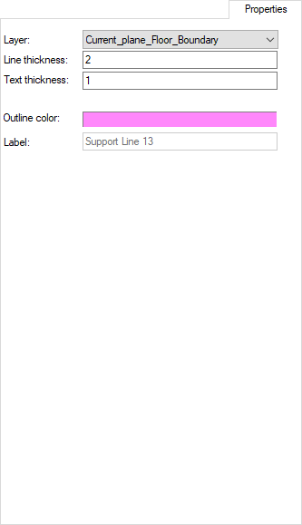
The corresponding inputs can be found in the Appearance tree of the Properties Grid when a support line is selected.
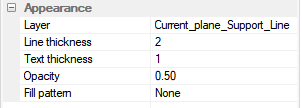
The following table provides a description for each of the support line layer properties that are available on the Properties tab.
Properties for the Support Line Layer
| Property Value(s) | Description |
|---|---|
| Layer |
Shows the current CAD layer the support line is associated with. To select a different layer:
Alternatively, you can select the support line and use the By Layer icon in the Modify ribbon to modify the support line's layer. |
| Line thickness |
Displays the current thickness of the support line on plan. To change the thickness of the support line shown on plan:
|
| Text thickness |
Displays the current thickness of the text along the support line. To change the thickness of the text along the support line:
|
| Outline color |
Shows the color currently being used for the selected support line.. To change the color of the support lines for the selected layer:
|
| Label |
Displays the label of the currently selected support line. This property is editable only through the Support Line properties General tab. . |
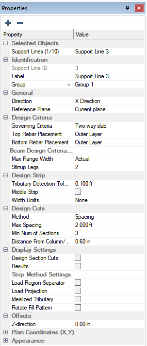
After the entry of support lines, it is important to set the properties of the support line to achieve a correct design. This includes setting the Design Criteria property that controls the design of the support line as either one-way, two-way, or beam criteria. The properties of the one-way, two-way and beam criteria are set in the Design Criteria panel. You can set the support line settings one support line at a time or for multiple support lines using the Properties Grid. To set properties of the support line please complete the following. In addition to the below methods of modifying support line properties, you have the ability to modify some of the support line properties using the Dynamic Editor. Please see the Dynamic Editor topic for more information.
To set support line properties in the properties grid:
Select one or more support lines you want to change the properties of.
Typically, you set the support lines properties for one direction of support lines at a time.
Modify the support line properties as needed for the design of the slab within the Properties Grid.
The following image shows the inputs that can be set for support lines.

Click on image to enlarge it
Once you've set the properties of the support lines appropriately for your design, you can have the program generate the tributaries and design sections for the support lines automatically (see Generate Automatic Design Sections). In addition, you can choose to manually enter tributaries and have the program generate the design sections based on the support lines and tributaries entered manually (see Enter Manual Tributaries).
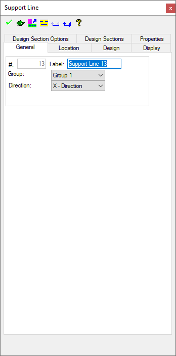
To set support line properties in the support line item properties window:
Double click on a support line you want to change the properties of to open the Support Line Item Properties window.
Click on image to enlarge it
Find and modify the input in the Support Line Properties Dialog tabs.
Click on the ![]() icon to accept the modifications.
icon to accept the modifications.
Click on the  icon to close the window.
Once you've entered support lines for both directions and set their properties correctly for your design, you can have the program generate the tributaries and design sections for the support lines automatically (see the Create Design Sections topic for more information). In addition, you can choose to manually enter tributaries and have the program generate the design sections based on the support lines and tributaries you entered (see Support Line Tributaries topic for more information).


