The program provides you two options for creating design sections to be investigated or designed within the model. You can either Generate Design Sections Automatically or Add Design Sections Manually. The following sections describe the two different methods and their use.
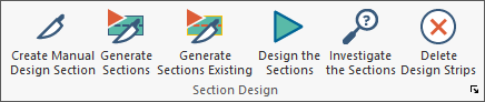
The tools for adding design sections to the model are in the Floor Design ribbon, Section Design panel.
In the process of Generating Design Sections Automatically the program determines the tributary areas assigned to the support line based on the support line width limit properties, automatically creates the tributary areas for the support line, and creates the design section cuts along the support line.
To generate design sections automatically:
To generate design sections, first enter the support lines in the model. For more information on entering support lines please view the Support Line topic of this help menu. The figure below shows an example of a model with support lines generated in both directions.
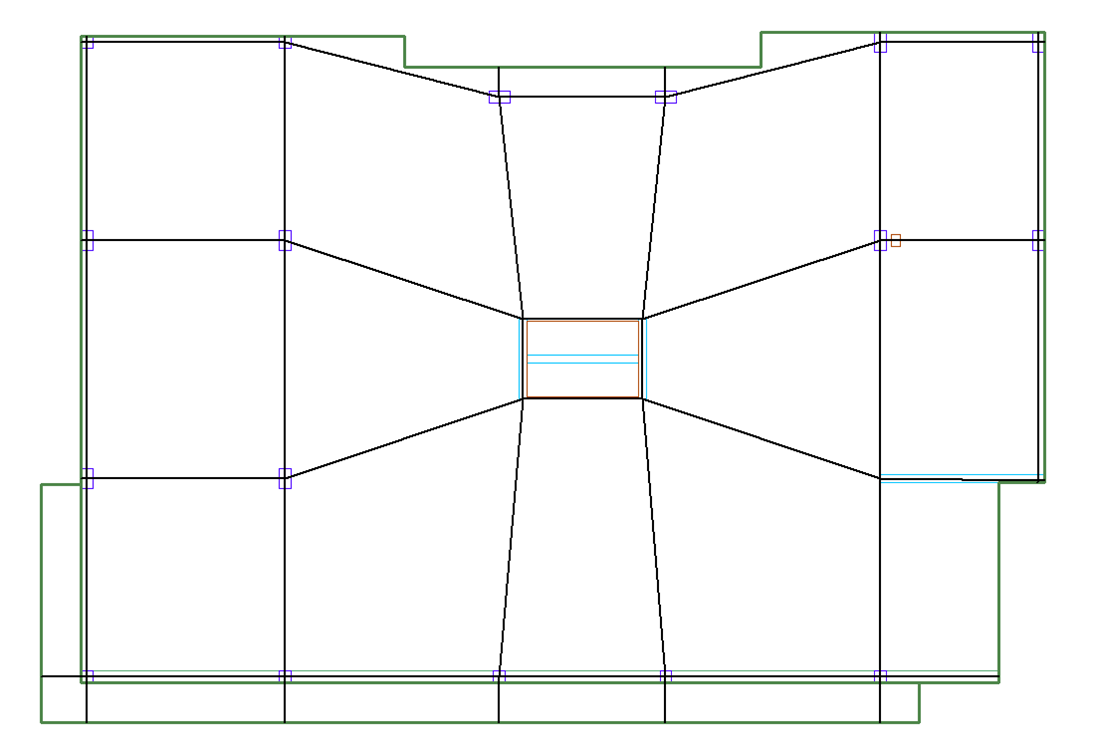
Click on image to enlarge it
The method to use to generate design sections depends on the state the tributaries are currently in.
If the tributary areas of the support lines have been generated automatically, go to the Floor Design ribbon, and click on the Generate Sections  icon.
icon.
If the tributary areas of the support lines have been generated automatically and then edited, or if the tributaries have been created manually, go to the Floor Design ribbon, and click on the Generate Sections Existing  icon.
icon.
Once the process is completed, the sections show along the support line on screen (as shown in the image following step 3).
If the process completes and no sections are shown, click on the Display Design Section ![]() icon of the Floor Design ribbon to display the sections.
icon of the Floor Design ribbon to display the sections.
Once completed, the view of the model should be similar to the view in the following example.
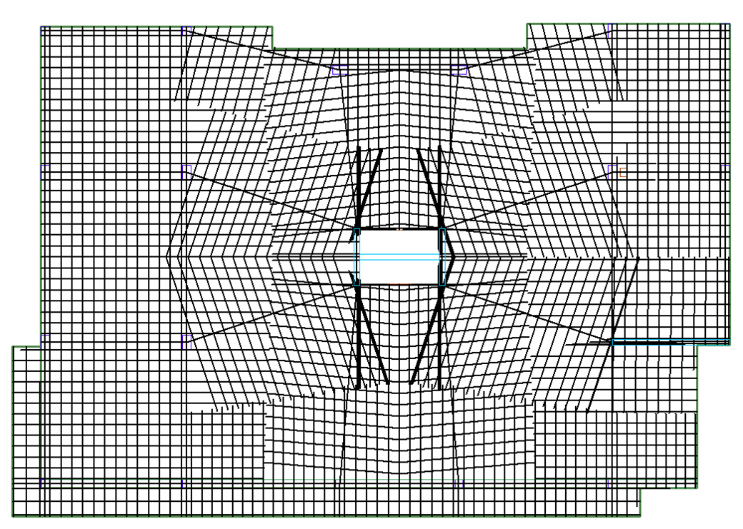
Click on image to enlarge it
Once the sections have been generated you have the option to Design the Design Sections or you can Investigate the Sections.
In addition to automatically generated design sections shown along the support line, you have the ability to enter manual design sections in any location within their slab.
To create a manual design section:
In the following example, we can see a location where the automatic design sections did not cut up to the face of the beam in the circled location.
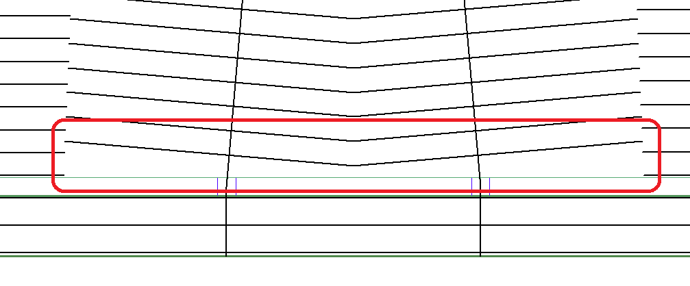
Click on image to enlarge it
Based on the previous image, to enter manual design sections in this location:
Go to the Floor Design ribbon and click on the Create Manual Design Sections  icon.
icon.
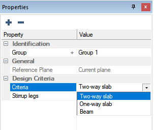
In the property grid, choose the design criteria (two-way, one-way, and beam) that you want used for the section.
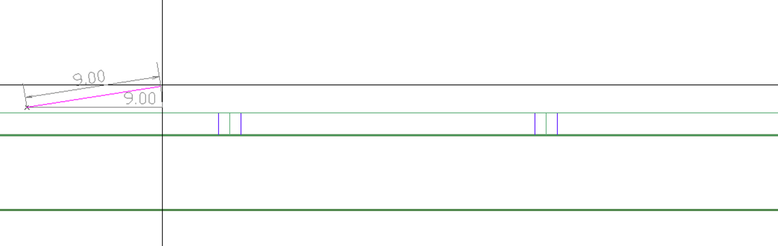
Without any snap tools turned on, left click the location where you want the first point of the section entered in the model.
Click on image to enlarge it
Once the first point is entered move the mouse to the location where you want the design section to end and left click.
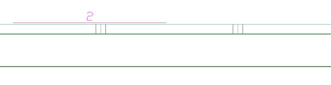
You now have a manual design section in the model. Manual design sections are represented by a thin pink line as shown in the following example.
Click on image to enlarge it
In the example, we have turned off the support line and turned on the manual design section ID for a clearer view of the manual design section. Manual design sections will be designed by the program, and you can display the design section actions and read rebar information at each manual design section.
(Optional) Repeat steps 2 - 4, to enter as many manual design sections as you want the program to evaluate in the design.
Once the sections have been generated, you have the option to Design the Design Sections or you can Investigate the Sections.