Support Line Tributary Regions
Support line tributary regions break the model into design strips along the support line. Once support lines and splitters have been entered into a model, you can Create Tributary Regions Automatically or Create Tributary Regions Manually. If the tributaries are created automatically, the user retains the ability to Modify Tributary Regions as needed.
Create Tributary Regions Automatically
The program will automatically generate tributaries during the generation of automatic design sections.
To create support line tributary regions automatically:
-
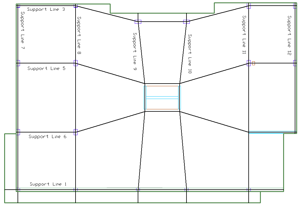
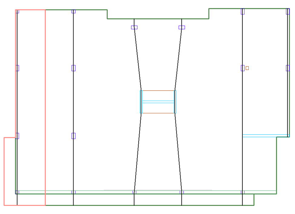
Enter the support lines in the model. Refer to the Support Line topic for more information on creating support lines. The figure below shows an example of a model with support lines generated in both directions.
Click on image to enlarge
-
Modify the Support Line Width Limits in the Properties Grid or using the Dynamic Editor.
-
Create Middle Strip Support Lines using the Dynamic Editor if applicable.
-
Go to Floor Design>Section Design and click on the Generate Sections  icon.
icon.
-
Once the process is completed, go to Floor Design> Strip Results/Visibility and click on either the Display/Hide Support Line Tributaries in X-direction or Display/Hide Support Line Tributaries in Y-direction icon as marked below.

-
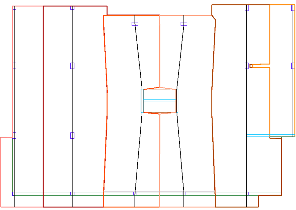
The tributary regions will display on the screen for that direction. An example of Y-Direction tributary regions for our example model is shown below. The user may need to turn off the design sections by going to Floor Design>Section Design and click on the Display Design Sections icon to see a view similar to the image below.
Click on image to enlarge
-
The tributary regions can then be modified if needed. Refer to the Modify Tributary Regions section for more information.
-
The user can turn on and off the display of the support line tributary regions in the Visibility Grid as well as using the tools in the Floor Design>Strip Results/Visibility panel.
Create Tributary Regions Manually
A user has the option to enter support line tributary regions manually rather than have the program generate them automatically.
Note: If tributaries are entered manually or automatically and then edited, you must use the Floor Design>Strip Results Visibility panel Generate Sections Existing tool to generate the design sections.
To create support line tributary regions manually:
-
Enter the support lines in the model. Refer to the Support Line topic for more information on creating support lines. The figure below shows an example of a model with support lines generated in both directions.
Click on image to enlarge
-
Create Middle Strip Support Lines using the Dynamic Editor if applicable.
-
Go to Floor Design>Strip Results/Visibility and click on either the Display/Hide Support Line in X-direction  or Support Line Tributaries in Y-direction
  icon to turn on the support lines in one direction.
-
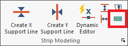
Go to Floor Design>Strip Modeling and click on the Create Support Line Tributary  icon marked in the image below.
-
Left-click your mouse on a the support line you wish to create a tributary region for.
-
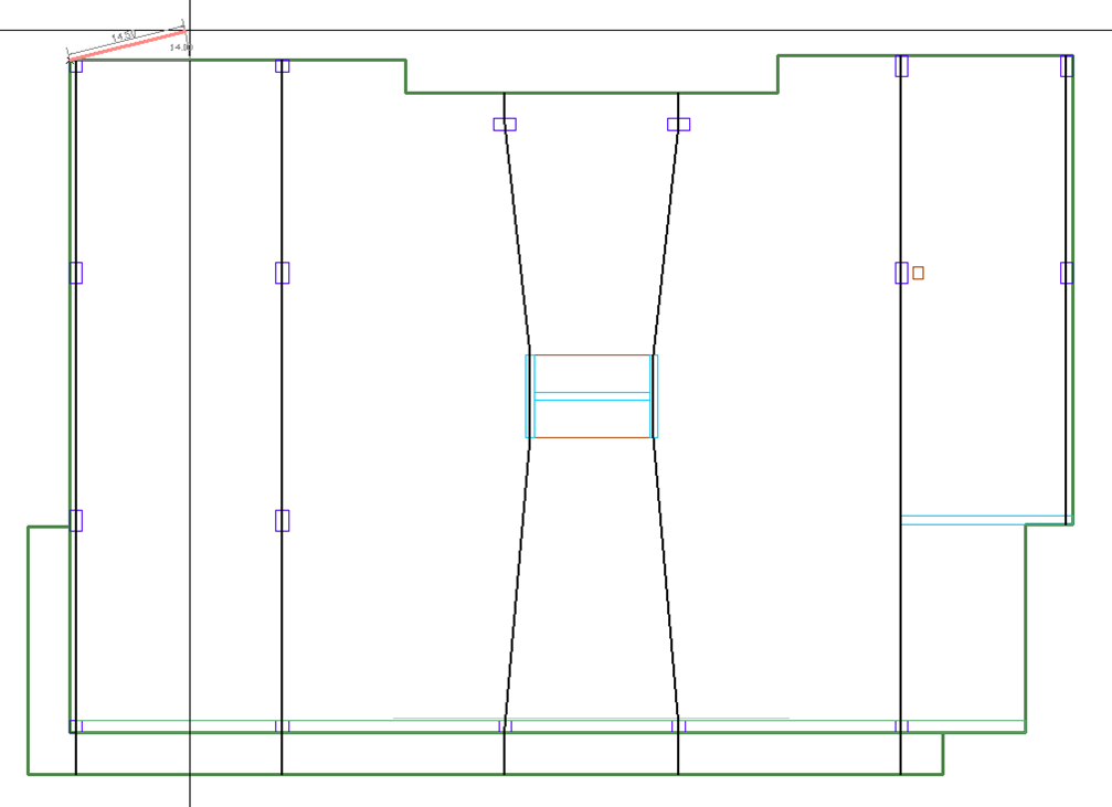
Left click your mouse to insert the first point of the tributary region. An example after doing so is shown in the image below.
Click on image to enlarge
-
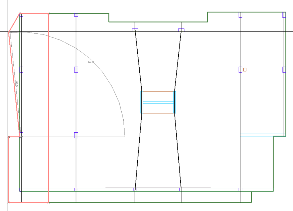
Continue using the mouse and left clicking at the locations the tributary region should follow.
Click on image to enlarge
-
To finish drawing the tributary region, right click and choose Close/End/Accept from the right click menu or click C on your keyboard.
Click on image to enlarge
-
Right click and choose Exit or press the ESC key on your keyboard to close out the tributary entry tool.
-
Repeat steps 3 through 9 to enter the rest of the tributaries into the model. An example of completed tributary regions for the Y-direction support lines in our example model is shown below.
-
After creating the support lines manually, you must use the Floor Design>Strip Results Visibility panel Generate Sections Existing  icon to generate the design sections
Modify Tributary Regions
The user has the option to edit automatically or manually generated tributaries once they have been created. The user can display the tributaries and edit the tributary vertices using the mouse to grab them and place them in another location. Additionally, the user can use the Add Vertexes/Delete Vertexes tools of the right click menu to add vertices to the tributary to modify their shape further.
Note: If tributaries are entered manually or automatically and then edited, you must use the Floor Design>Strip Results Visibility panel Generate Sections Existing tool to generate the design sections.