You have two options for entering middle strip support lines in the model. You can enter middle strip support lines into a model using the dynamic editor in most models. However, in some more complex slab layouts, you may choose to enter middle strip support lines manually. Regardless of which option you choose, you always have the ability to edit the middle strip support lines after entry.
The Dynamic Editor and the tools for Manual Entry of support lines are in the Floor Design ribbon, Strip Modeling panel. Detailed steps on using both entry options are outline below.
To enter middle strip support lines into a model using the Dynamic Editor:
Create Column Strip Support Lines for the model.
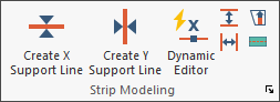
Go to the Floor Design ribbon.
Click on Dynamic Editor.
![]()
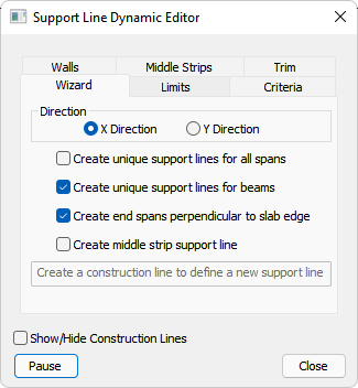
The Dynamic Editor opens to the Wizard tab.
Click the Middle Strips tab, to open the Middle Strips panel.
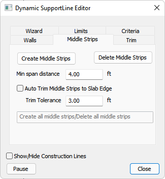
Set the options you want to use, to have support lines created in the fashion you consider most fit for your model. Checked boxes indicate that the option is chosen; unchecked indicates that it is not.
For more information on these inputs and their behavior, see the Dynamic Editor topic.
Click the Create Middle Strips button.
The middle strips appear as blue lines in the model, as shown in the following image.

Click on image to enlarge it
If the middle strips need adjusting, adjust the inputs of the Dynamic Editor Middle Strips panel and then click the Create Middle Strips button again.
Repeat step 6 until you have acceptable middle strips displayed.
Once the blue middle strips look acceptable, Close the dynamic support line editor to create the middle strips in the model. These support lines can be manually adjusted after entry, as well.
The program automatically sets the middle strip property when generating middle strips with the Dynamic Editor. The middle strip property is in the Design Strip tree of the Property Grid with a support line selected (as shown in the following image).

After entering the middle strip support lines you must set the properties of each support line to be used during the design section creation and design phases of the program . See the Support Line Properties topic for more information on where and how to set the support line properties after their creation.
To enter middle strip support lines into the model manually:
Go to the Floor Design ribbon.
Click on the Generate Sections icon to have the program automatically generate the tributary areas and design sections for the column strip support lines.

Click on the Display/Hide Support Lines in Y-Direction icon in the Strip Results/Visibility panel.
![]()
Click on the  Display/Hide Support Line Tributaries in Y-Direction icon under Strip Results/Visibility, to turn on the support line tributary areas.
The following example is of the Y-direction support lines and tributary areas both being displayed.

Click on image to enlarge it
Click on the Create Y Support Line icon under Strip Modeling on the Floor Design ribbon.
![]()
In the Properties Grid, expand the Design Strip tree.
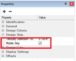
Check the Middle Strip option.
Turn on the  Snap to End point tool in the bottom quick access toolbar.
Hover your mouse over the location where you want to start the middle strip support line, until the snap to end point icon appears on the mouse pointer.
Typically, this is the location where two tributaries meet, as shown in the following image.

Click on image to enlarge it
Move your mouse along the tributary until you get to the next line of columns.
Once the mouse is in the correct location, left click and place a support line vertex in this location.
While there is no support here, it is important that a vertex is placed in this location so the program understands the span lengths along the support line (as shown in the following image).

Click on image to enlarge it
Continue step 10 until you reach the outer slab edge of the model.
Once you have placed the last point at the slab edge, right-click and choose Close/End/Accept to finish the modeling of this middle strip support line
Alternatively, press C on your keyboard.

Click on image to enlarge it
Repeat steps 7 - 12 to place the other middle strip support lines in the Y-direction. When finished the example model would look similar to the below image.

Click on image to enlarge it
Once the last support line in this direction has been entered, right click and choose Exit to close out of the support line modeling.
Alternatively, press ESC on your keyboard.
Using the ![]() Create X Support Line tool, follow the same procedure for the X-direction support lines.
Create X Support Line tool, follow the same procedure for the X-direction support lines.
Once X-Direction middle strips have been entered, your model should look similar to the following example.

Click on image to enlarge it
After entering the middle strip support lines, you must set the properties of each support line to be used during the design section creation and design phases of the program . See the Support Line Properties topic for more information on where and how to set the support line properties after their creation.