You have two options for entering column strip support lines in the model. You can enter support lines into a model using the dynamic editor in most models. However, in some more complex slab layouts, you may choose to enter support lines manually. Regardless of which option you choose, you always have the ability to edit the support lines after entry.
The Dynamic Editor and the tools for Manual Entry of support lines are in the Floor Design ribbon, Strip Modeling panel. Detailed steps on using both entry options are outline below.
To enter column strip support lines into a model using the Dynamic Editor:
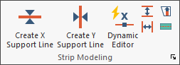
Go to the Floor Design ribbon.
Click on the Dynamic Editor icon.
![]()
The Dynamic Editor opens to the Wizard tab. See the Dynamic Editor topic for a detailed description of all the tools within.
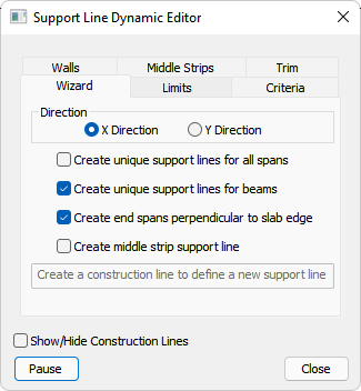
Choose the X-Direction or Y-Direction option, to input support lines for the slab in the first direction.
Check the box(es) of the options you want to use to have support lines created in the fashion you consider most fit for your design. Checked boxes indicate that the option is chosen; unchecked indicates that it is not.
For more information on these inputs refer to the Dynamic Editor topic.
When finished changing the settings, the program prompts you to draw the construction line used to find supports for the support line.
Move your mouse outside of the slab region, next to the first support in the line of support.
Left-click to designate the starting point of the construction line.
As you move your mouse from where you clicked, a red line from that point to the current mouse position appears (as shown in the following image).

Click on image to enlarge it
You can now cross over supports with the construction line, following the rules of member recognition.
The following image shows an example of a construction line going through columns, walls, and transverse walls. A small red circle along the construction line denotes the location of each mouse click when entering the construction line.

Click on image to enlarge it
Right-click and choose Close/End/Accept to close the construction line modeling and have the program create the support line.
Alternatively, press C on your keyboard.
The following image is an example of the support line in the model.

Click on image to enlarge it
Repeat steps 5 - 7, until you have defined a support line for each line of support for the first direction of your model.

Click on image to enlarge it
Click the Wizard tab in the Dynamic Editor.
Click on the Y Direction option, to create the support lines for the second direction.
Repeat steps 4 - 8, until you have defined support lines for the opposite direction in the model, as shown in the following image.

Click on image to enlarge it
After entering the column strip support lines, you can either Create Middle Strip Support Lines, if applicable to the design, or set the properties of each support line to be used during the design section creation and design phases of the program. See the Support Line Properties topic for more information on where and how to set the support line properties after their creation.
To enter column strip support lines into the model manually:
Go to the Floor Design ribbon.
Click on Create X Support Line icon.
![]()
With only the snap to perpendicular snap tool activated, left-click along the slab edge to enter the first vertex of the support line (as shown in the following image).

Click on image to enlarge it
 Snap to End Point tool.
 Hover your mouse over the first support along the line of support.
Left-click to enter a support line vertex at the first support location (as shown in the following image).

Click on image to enlarge it
Hover your mouse over the next support along the line of support you are entering the support line for.
Left-click to place the next support line vertex.

Click on image to enlarge it
Continue placing a support line vertex at each support, until you have reached the last support along the line of support.
Click on image to enlarge it
Once you have snapped to the last support along the line of support, turn off the ![]() Snap to End Point tool and turn on the
Snap to End Point tool and turn on the ![]() Snap to Perpendicular tool.
Snap to Perpendicular tool.
Hover your mouse over the slab edge at the end of the line of support.
Left-click to place the last vertex.

Click on image to enlarge it
Right-click and choose Close/End/Accept, to finish the entry of the first support line.
Alternatively, press C on your keyboard.

Click on image to enlarge it
Repeat steps 3 - 13, until you have defined a support line for each line of support for the first direction of your model.
Right-click and choose Exit to close out of the support line modeling tool.
Alternatively, press Esc on your keyboard. The image below shows the slab after all X-direction support lines have been entered into the model.

Click on image to enlarge it
Go to the Floor Design ribbon.
Click on Create Y Support Line.
![]()
Follow a similar workflow as described in steps 3 - 14, to define a support line for the opposite direction in the model as well.
Right-click and choose Exit to close out of the support line modeling tool.
Alternatively, press Esc on your keyboard. The image below shows the slab after all Y-direction support lines have been entered into the model.

Click on image to enlarge it
After entering the column strip support lines, you can either Create Middle Strip Support Lines, if applicable to their design, or set the properties of each support line to be used during the design section creation and design phases of the program. See the Support Line Properties topic for more information on where and how to set the support line properties after their creation.