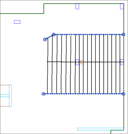
In the case of more complex structural layouts, splitters are available to aid in customizing the design strips. Splitters limit the width of the design strip to the location of the splitter for the length of the splitter. Splitters must be associated with the correct support line direction. If the intent is to limit the width of a tributary region associated with an X-direction support line, you must enter an X-direction splitter. The same is true for the Y-direction.
You can find the Create X Splitter and Create Y Splitter tools in the Floor Design > Strip Modeling panel as marked in the following figure.
![]()
To input splitters:
Go to Floor Design > Strip Modeling and click on either the Create X-direction Splitter  or Create Y-direction splitter
  icon.
icon.
Move your mouse to the start point of where you want the splitter to start in the model and left click the mouse to enter the first point of the splitter.
Move your mouse to the end point of where you want the splitter to end in the model and left click the mouse to place the end point of the splitter.
Right click and choose Close/End/Accept or click C on your keyboard, to close out the modeling of the splitter.
Repeat steps 1 - 4 until all splitters have been entered in the model.
Right-click and choose Exit to close out the modeling of splitters.
Once the support lines and splitters have been entered into the model you can Generate the Design Sections Automatically to see the tributary and design section layout.
The below figure shows a model with one support line entered, with splitters entered to limit the width of the tributary for the support line. A user could decide to design this isolated area using this technique as well.
