
For soil supported slabs, distribute the support lines across the slab, with spacing between five and ten feet. Place vertices along the support line at locations where supports from above land on the soil supported slabs, to ensure that the support lines see the correct spans in the MAT/footing/or strip footing. The following image illustrates a model that consists of a MAT, one footing and one strip footing.
Click on image to enlarge it
To generate support lines for soil supported slabs:
The following steps do not have to be followed exactly to get a good distribution of support lines across the soil supported slab, rather the steps below should be seen as a guideline of the workflow for their creation.
Go to the Floor Design ribbon.
Click on Create X Support Line to define the support lines for the first direction.
![]()
Click the ![]() Snap to Perpendicular tool, to turn it on.
Snap to Perpendicular tool, to turn it on.
Left-click your mouse at the geometric center of the soil supported slab.
With the snap to perpendicular tool on, snap the second end of the support line to the opposite edge of the MAT slab.
Right-click and choose Close/End/Accept, to close the modeling of this support line.
Alternatively, press C on your keyboard.
Right-click and choose Exit, to close out of the support line modeling tool.
Alternatively, press ESC on your keyboard.
Once finished, you should have one support line at the center of the MAT, as shown in the following image.

Click on image to enlarge it
Hover your mouse over the support line entered.
Right-click and choose Insert Vertexes.
Left-click to add a vertex in line with the supports coming down on to the MAT along the support line.
Once finished, we have a support line with five spans along it, as shown in the following image.

Click on image to enlarge it
Select the support line, go to the Modify ribbon and click By Coordinates.
![]()
Enter the distance you want to copy the support lines and then the number of times you want to copy the support line.
In the following example, we entered five feet for the distance and ten for the number of support lines we wanted copied.

Click Copy to close the dialog and copy the support lines.

Click on image to enlarge it
With the master support line still selected, go to the Modify ribbon.
Click the By Coordinates icon.
![]()
Enter a negative value to copy the support line down in the model.
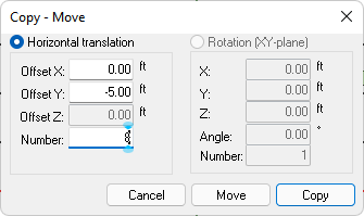
Click Copy to close the dialog and copy the support lines.

Click on image to enlarge it
In the Dynamic Editor, click the Trim tab to trim/extend tendons to the slab edge.
For information on the Trim tab and its use please refer to the Dynamic Editor topic of this help menu.
Using your mouse, adjust the support lines such that the vertices of the support line follow the line of support between supports.
After the modifications, our example looks like the following image. Selected support lines appear in red, which helps to show the location of the vertices along the support line.

Click on image to enlarge it
Go to the Floor Design ribbon.
Click on Create Y Support Line, to define the support lines for the second direction.
![]()
Repeat a similar workflow as outlined in steps 3 - 19, to create support lines in the opposite direction.

Click on image to enlarge it
Repeat a similar workflow as outlined in steps 1 - 22, to create the support lines for the strip footing and footing slabs.
The following images provide an example of support lines in both X and Y directions.
Examples:
X-Direction Support Lines:

Click on image to enlarge it
Y-Direction Support Lines:

Click on image to enlarge it