ADAPT-Builder provides the user with the ability to add post-tensioning to ramps modeled within the program. The user can add Tendons In Ramps as well as add Tendons in Ramp Beams. The tendons and effects of the tendons on the structure will be included in the analysis of the model. Tendons modeled within ramps must be added using the Add Tendon tool as the mapping tools and smart tendon tools do not account for the ramp component. Tendons created by the mapping tools and the smart tendon tools near ramps should be reviewed carefully.
In the below example we will model a tendon in a slab, and continue the tendon through to the ramp. The below example is a four-span, two-cantilever structure with a ramp sloping down from the main deck.
-
Click on the Add Tendon  icon of the Tendon ribbon Model panel.
-
Set the Tendon Properties for the tendon to be modeled in the Properties Grid. Make sure to check the connect to ramp property when you want the tendon located within the ramp component.
-
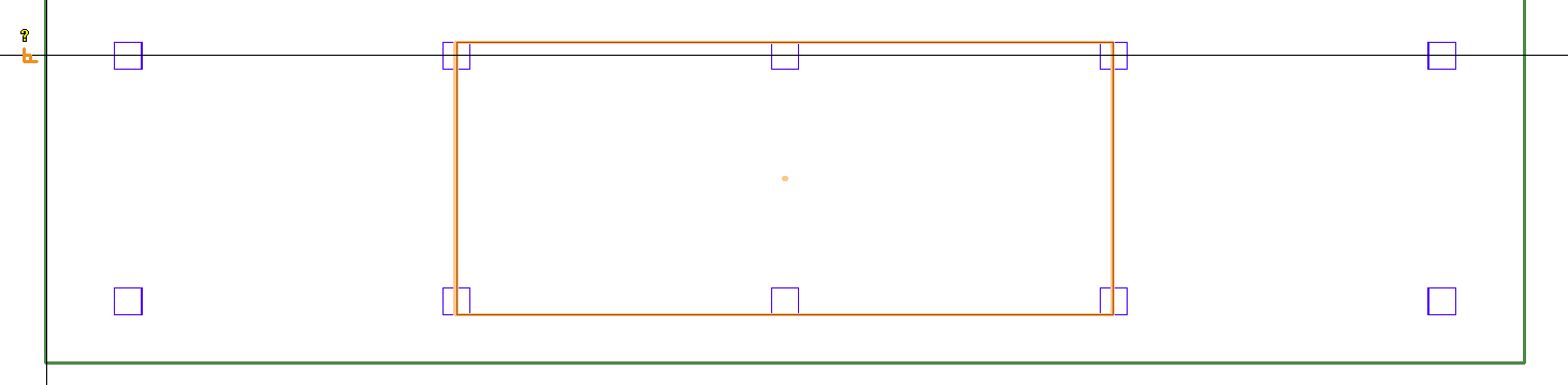
Click on the Snap to Perpendicular  icon on the bottom quick access toolbar to activate the snap tool. Make sure all other snap tools are inactive.
-
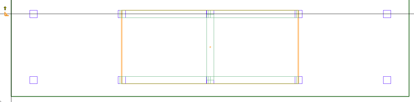
Position your mouse over the slab edge and left-click to place the first point of the tendon.
Click on image to enlarge it
-
Click on the Snap to Perpendicular icon on the bottom quick access toolbar to deactivate the snap tool.
-
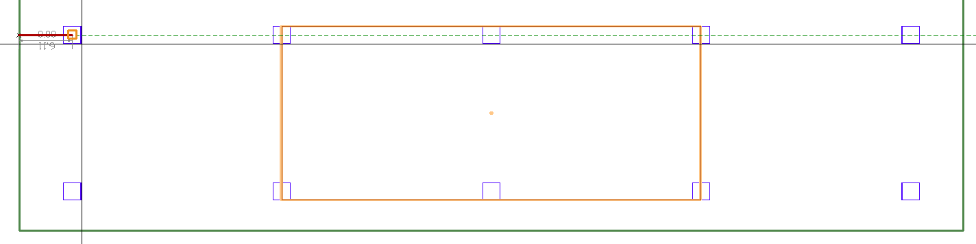
Click on the Snap to End Point  icon on the bottom quick access toolbar to activate the snap tool. Make sure all other snap tools are inactive.
-
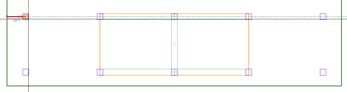
Move your mouse to the position of the second point along the tendon and left-click to place the second point of the tendon.
Click on image to enlarge it
Click on the Snap to End Point icon on the bottom quick access toolbar to deactivate the snap tool.
-
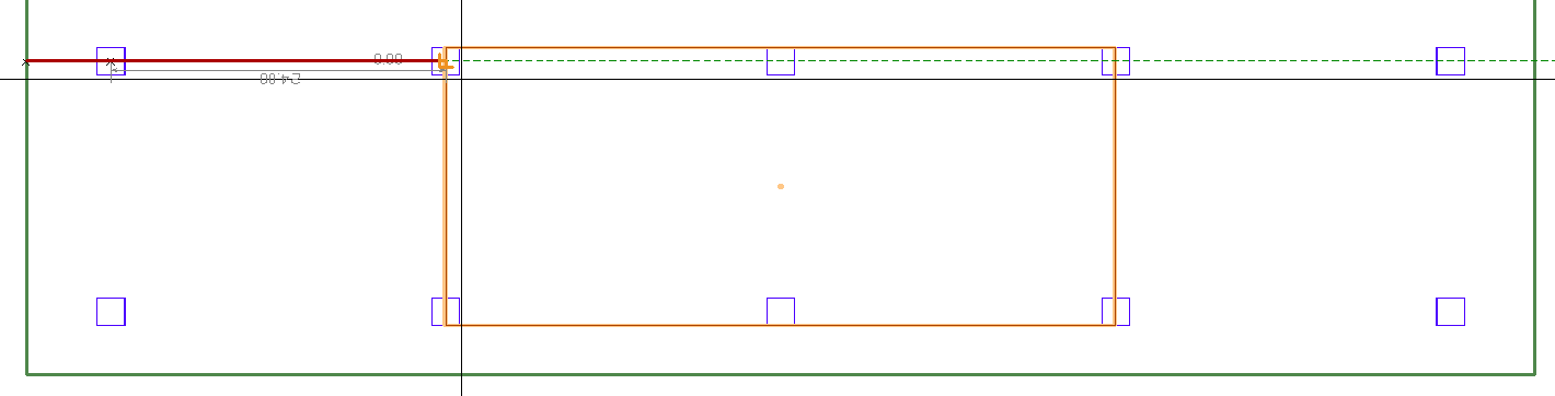
Click on the Snap to Perpendicular icon on the bottom quick access toolbar to activate the snap tool. Make sure all other snap tools are inactive.
-
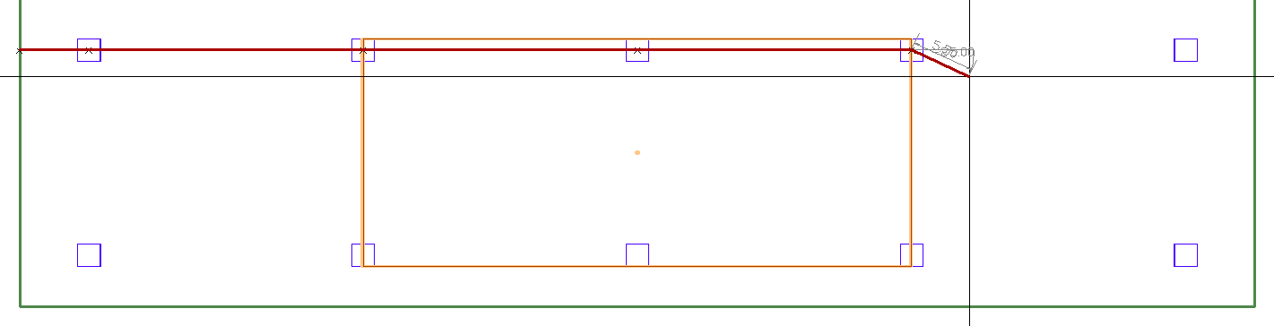
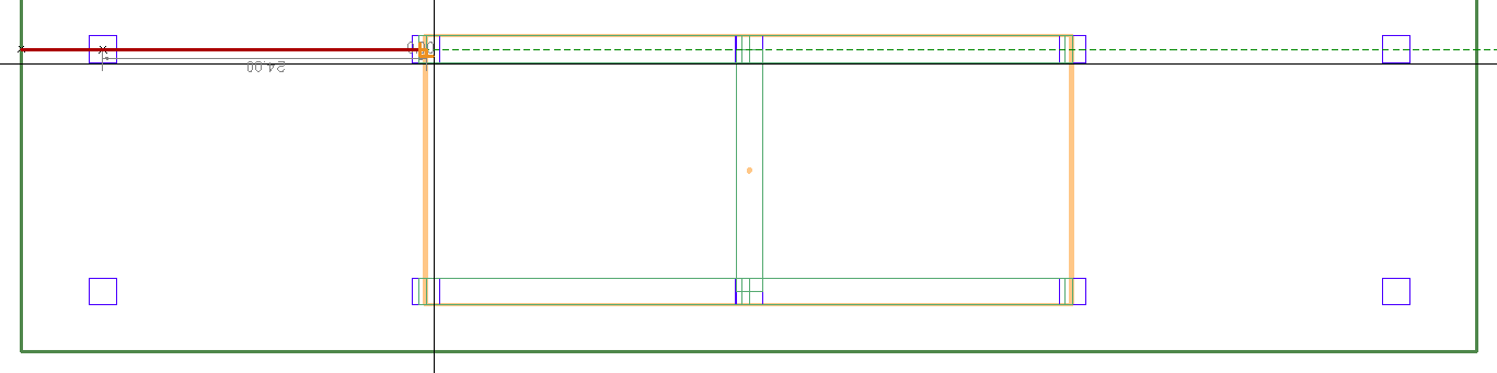
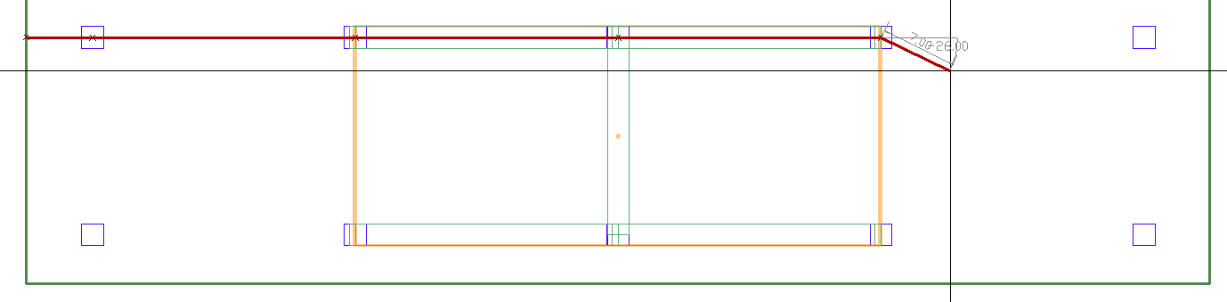
Move your mouse to the intersection of the slab and the ramp and left-click to place this point of the tendon.
Note: The user must model a tendon vertex at the location where the slab transitions to the ramp for the tendon to be properly accounted for within the ramp.
Click on image to enlarge it
-
Click on the Snap to Perpendicular icon on the bottom quick access toolbar to deactivate the snap tool.
-
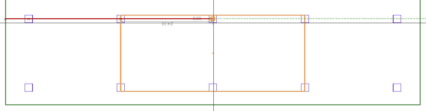
Click on the Snap to End Point icon on the bottom quick access toolbar to activate the snap tool. Make sure all other snap tools are inactive.
-
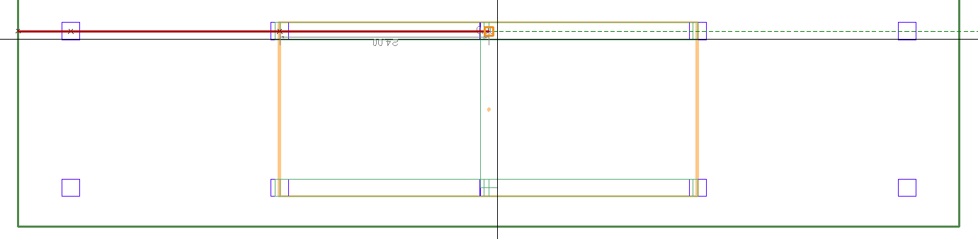
Move your mouse to the next location and left-click to create the next span
Click on image to enlarge it
-
Continue adding spans until you reach the end of the ramp. Make sure to stop the tendon at the bottom of the ramp.
Click on image to enlarge it
-
Click the Enter key or the C key on your keyboard to close out the modeling of the tendon. Alternatively, you can right-click and choose Close/End/Accept from the right-click menu.
Note: If the tendon is to continue into the slab in the plane below, the user will have to model that segment of the tendon in the below level. Make sure that the start point of the tendon in the slab below coincides with the end point of the tendon within the ramp above the slab.
Click on image to enlarge it
-
Repeat steps 1 through 14 to create any additional tendons you want located within the ramp or slab.
Note: Tendons along the short side of the ramp will be modeled in the same manner as the tendon along the long side of the ramp. Make sure to snap the tendon to the edge of the ramp component.
-
Click the Esc key on your keyboard to exit the tendon modeling tool when all tendons are modeled in the ramp.
Click on image to enlarge it
-
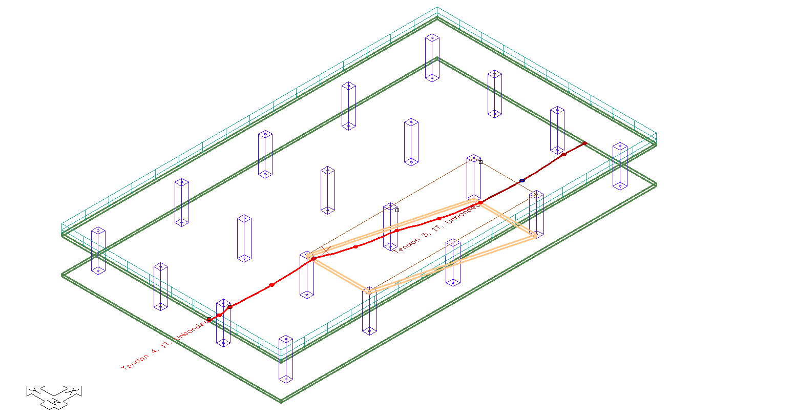
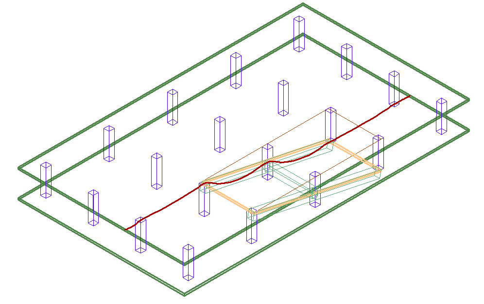
Click the Top-Front-Right view icon in the Bottom Quick Access toolbar to see the tendons in an isometric view.
Click on image to enlarge it
When beams are modeled along or transverse to the slope along a ramp, ADAPT-Builder will model tendons within the cross section of the beam, in reference to the beam. Tendons outside the cross-section of the beam and within the ramp will still be modeled in reference to the ramp.
In the below example we will model a tendon in a slab, and continue the tendon through to the beam within the ramp. We will also model a tendon within a beam transverse to the ramp slope. The below example is a four-span, two-cantilever structure with a ramp sloping down from the main deck. Beams are modeled along the two sloping edges with an additional transverse beam modeled at the center columns of the structure.
-
Click on the Add Tendon icon of the Tendon ribbon Model panel.
-
Set the Tendon Properties for the tendon to be modeled in the Properties Grid. Make sure to check the connect to ramp property when you want the tendon located within the ramp or a beam connected to the ramp.
-
Click on the Snap to Perpendicular icon on the bottom quick access toolbar to activate the snap tool. Make sure all other snap tools are inactive.
-
Position your mouse over the slab edge and left-click to place the first point of the tendon.
Click on image to enlarge it
-
Click on the Snap to Perpendicular icon on the bottom quick access toolbar to deactivate the snap tool.
-
Click on the Snap to End Point icon on the bottom quick access toolbar to activate the snap tool. Make sure all other snap tools are inactive.
-
Move your mouse to the position of the second point along the tendon and left-click to place the second point of the tendon.
Click on image to enlarge it
-
Click on the Snap to End Point icon on the bottom quick access toolbar to deactivate the snap tool.
-
Click on the Snap to Perpendicular icon on the bottom quick access toolbar to activate the snap tool. Make sure all other snap tools are inactive.
-
Move your mouse to the transition of the slab and the ramp/beam and left-click to place this point of the tendon.
Click on image to enlarge it
Note: The user must model the tendon within the cross-section of the beam component in order for the tendon to reference the beam. Tendons modeled outside the cross-section of the ramp component will reference the ramp or slab they are modeled within.
-
Click on the Snap to Perpendicular icon on the bottom quick access toolbar to deactivate the snap tool.
-
Click on the Snap to End Point icon on the bottom quick access toolbar to activate the snap tool. Make sure all other snap tools are inactive.
-
Move your mouse to the next location and left-click to create the next span.
Click on image to enlarge it
-
Continue adding spans until you reach the end of the ramp. Make sure to stop the tendon at the bottom of the ramp slope.
Click on image to enlarge it
Click the Enter key or the C key on your keyboard to close out the modeling of the tendon. Alternatively, you can right-click and choose Close/End/Accept from the right-click menu.
Note: If the tendon is to continue into the slab in the plane below, the user will have to model that segment of the tendon in the below level. Make sure that the start point of the tendon in the slab below coincides with the end point of the tendon within the ramp above the slab.
Click on image to enlarge it
-
Repeat steps 1 through 14 to create any additional tendons you want located within the beam sloping with the ramp.
Click on image to enlarge it
-
Click the Esc key on your keyboard to exit the tendon modeling tool when all tendons are modeled in the ramp.
-
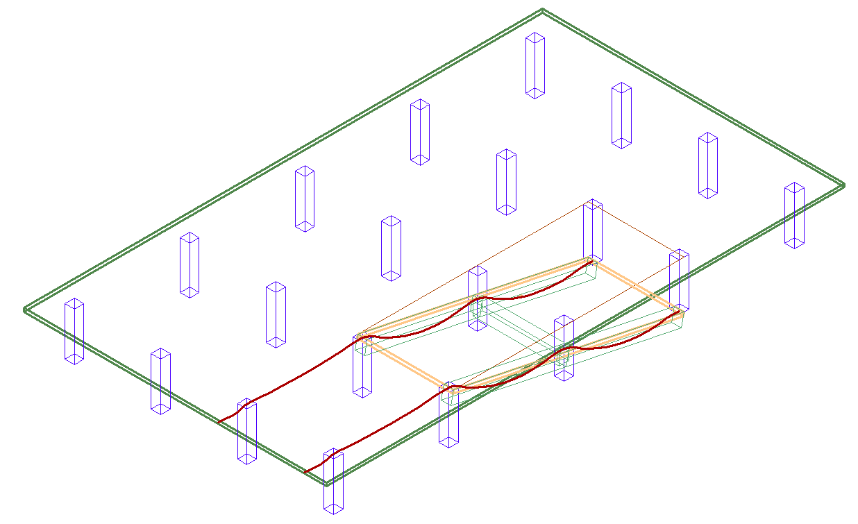
Click the Top-Front-Right view icon in the Bottom Quick Access toolbar to see the tendons in an isometric view.
Click on image to enlarge it
-
Click on the Add Tendon icon of the Tendon ribbon Model panel.
-
Set the Tendon Properties for the tendon to be modeled in the Properties Grid. Make sure to check the connect to ramp property when you want the tendon located within the ramp component.
-
Click on the Snap to Perpendicular  icon on the bottom quick access toolbar to activate the snap tool. Make sure all other snap tools are inactive.
-
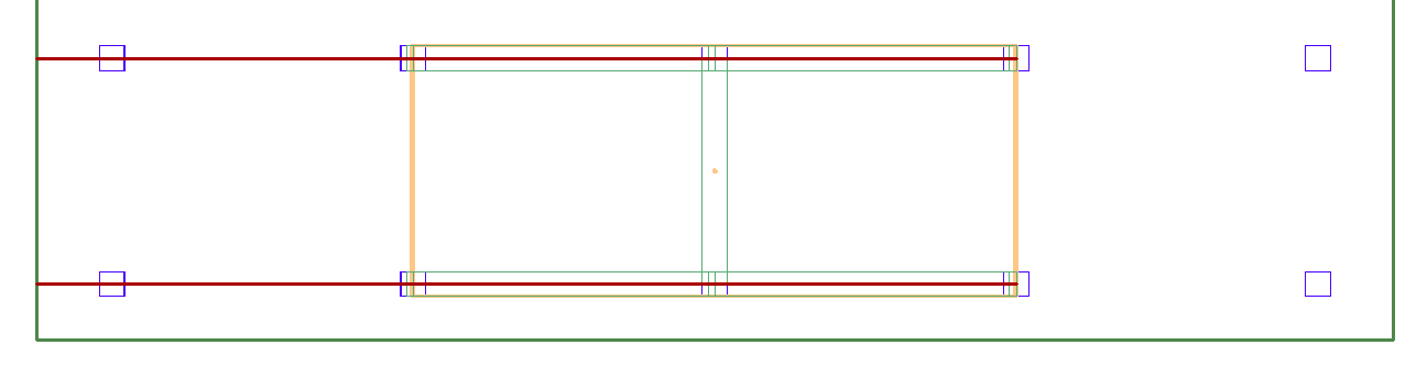
Position your mouse over the ramp edge and left-click to place the first point of the tendon.
Click on image to enlarge it
-
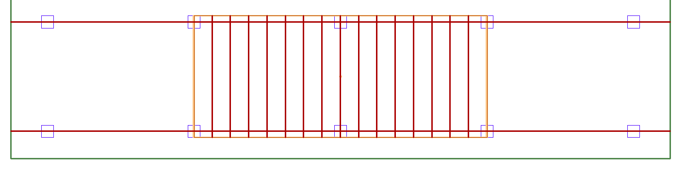
Move your mouse to the position of the opposite slab edge and left-click to place the second point of the tendon.
Note: The user must model the tendon within the cross-section of the beam component in order for the tendon to reference the beam. Tendons modeled outside the cross-section of the ramp component will reference the ramp or slab they are modeled within.
Click on image to enlarge it
-
Click the Enter key or the C key on your keyboard to close out the modeling of the tendon. Alternatively, you can right-click and choose Close/End/Accept from the right-click menu.
-
Click the Esc key on your keyboard to exit the tendon modeling tool.
-
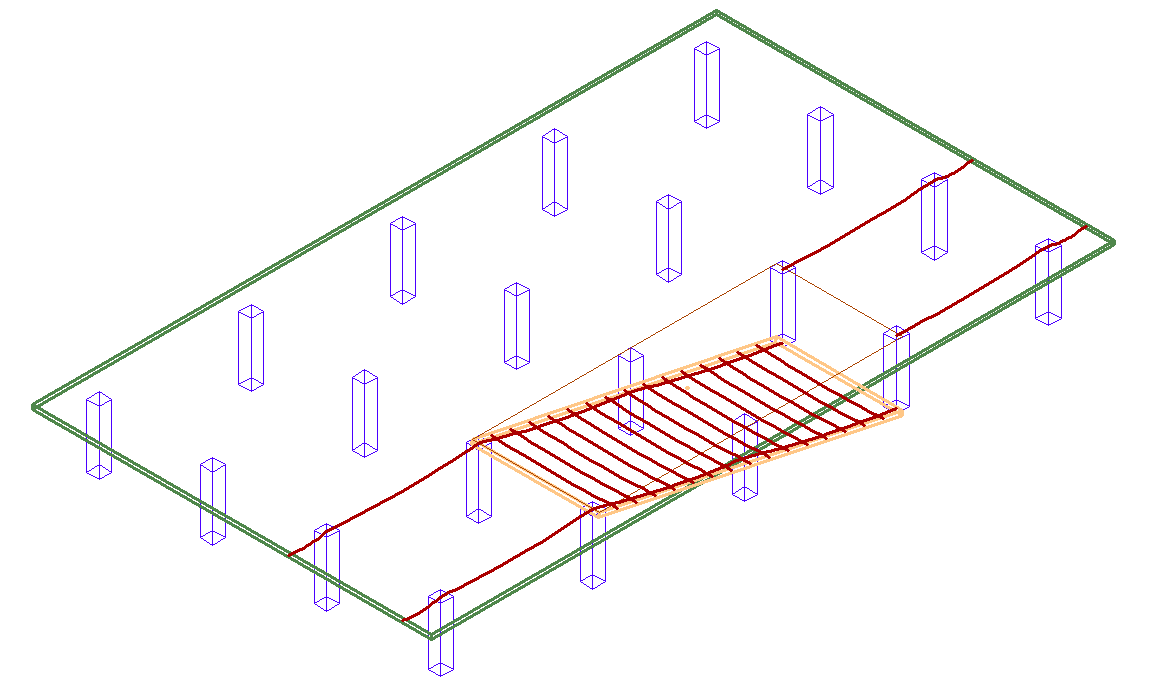
Click the Top-Front-Right view icon in the Bottom Quick Access toolbar to see the tendon in an isometric view.
Click on image to enlarge it